|
<< Click to Display Table of Contents >> Creating Staged Dumps for Strips 3 & 4. |
  
|
|
<< Click to Display Table of Contents >> Creating Staged Dumps for Strips 3 & 4. |
  
|
This and following topics describe the creation of three Staged Dumps to accommodate material from the Strips 3 & 4 Supersequence described in the previous topics. The form of these dumps was described previously in the introductory topic Setting up a Two Strip Operation. It is strongly recommended that the material in this introductory topic be revised now so that you have a clear understanding of the required behaviour of the Staged Dumps we need to create.
The following Staged Dumps must be created:
Strip 2 Low wall Dump Top.
This dump commences with a lift at natural ground level and progresses up in 10 m lifts. It will be used to accommodate Ate and Boreas waste from Strip 4. The following figure shows the topography at the start of the Strip 2 Low wall Dump Top :
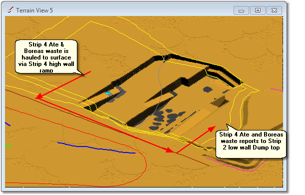
Strip 2 Low wall Dump Top.
The Strip 2 Pit Shell Surface incorporates a Dump in the low wall profile. The Strip 2 Pit Shell Surface will be used as a constraining surface for the Strip 2 Low wall Dump Top. This surface is shown in figure below:
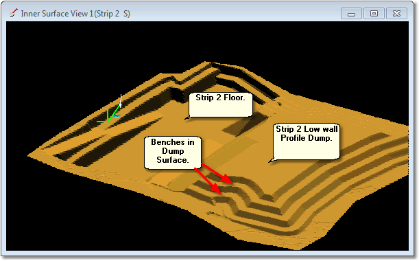
Strip 2 Pit Shell Surface Showing Low wall Profile Incorporating Dump.
The Strip 2 Low wall Dump Top Staged Dump has the following characteristics:
It is constrained by the low wall profile of the Strip 2 Pit Shell. The Strip 2 Pit Shell Surface has a low wall profile which incorporates a complete dump surface. This surface is therefore the upper pass surface for the Staged Dump.
Dumping in the Strip 2 Low wall Dump Top commences with the trucks tipping off the endwall at ground level. The initial pass is therefore at ground level. The 3d-DigPlus file contains an Inner Surface called Pre-Mining Topography, this surface will be used as a Pass Surface for the Stage Dump. The initial pass will therefore be from the terrain to the Pre-Mining Topography surface. This pass will have only one lift as the trucks will be at this level when dumping and the endwall tip face will be advanced at this level throughout.
On completion of this initial pass the dumping will continue upward in 10 m lifts. Note that material has already been dumped within the Strip 2 low wall profile. The level is already very close to the level of the topography, therefore this initial ground level pass will contain only a small amount of material. The bulk of the Strip 2 Low wall Dump Top will be in the upper section from ground level up.
The material contained in the lower section of the Strip 2 low wall profile was dumped within the Strip 2 Base Dump. This dump exists in our 3d-DigPlus file and we will use it as the basis to create the Strip 2 Low wall Dump Top. This process is known as Superimposed Dumps.
The Strip 2 Low wall Dump Top Dump has the following Pass Surfaces:
•Terrain Surface
•Pre-Mining Topography Surface
•Strip 2 Pit Shell Surface
This results in the following passes with the following characteristics:
•Terrain Surface to Pre-Mining Topography surface. This is a Single Lift pass therefore it has no Lift Parameters. The Dump Direction is north to south.
•Pre-Mining Topography surface to Strip 2 Pit Shell Surface. This surface is to have multiple 10 m lifts. Therefore the multiple lifts option is selected and the Bench Height for Lifts is set to 10 m. The benches are to be horizontal therefore the Use Horizontal Benches option is selected. The Lift Benches are required to match up with benches in the constraining surface, to achieve this the Use Horizontal Benches option is selected with the Fixed Bench Levels option. The Set Level parameter is set to 600 m which will ensure that the lift benches matchup with benches in the design surface. The dump direction for all lifts is north to south.
The following figure shows a cross-section through the Strip 2 Low wall Dump Top:
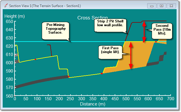
Strip 2 Low wall Dump Top Cross-Section.
Strip 3 Low wall Dump Base.
The Strip 3 Pit Shell surface incorporates a Dump in the low wall profile similar to the Strip 2 Pit Shell surface shown above. The strip 3 Low wall Dump Base is constrained by the Strip 3 Pit Shell surface. This Dump commences with the lift at pit floor level, and progresses up in 10 m lifts.
The Strip 3 Low wall Dump Base is used to contain material from the Strip 3 Chione waste passes.
The following figure shows the topography at the start of the Strip 3 Low wall Dump Base Dump:
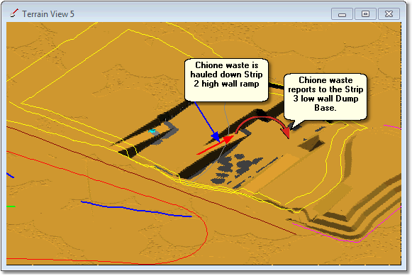
Strip 3 Low wall Dump Base Dump.
The Strip 3 Low wall Dump Base has the following characteristics:
It is constrained by the Strip 3 Pit Shell low wall profile surface.
Dumping commences at pit floor level and progresses up in 10m lifts in the direction from south to north.
The The Dump Area extends from the Strip 3 low wall toe up dip to encompass the Strip 2 void.
This dump has only two Pass Surfaces and therefore one Pass. The Pass Surfaces are:
•The Terrain Surface.
•The Strip 3 Pit Shell Surface.
The multiple lifts option is selected and the Bench Height for Lifts is set to 10 m. The benches are to be horizontal therefore the Use Horizontal Benches option is selected. The benches are required to match up with benches in the constraining surface, to achieve this the Fixed Bench Levels option is selected. The Set Level parameter is set to 600 m which will ensure that the lift benches matchup with benches in the design surface. The dump direction for all lifts is south to north.
The following figure shows a cross-section through the Strip 3 Low wall Dump Base Dump:
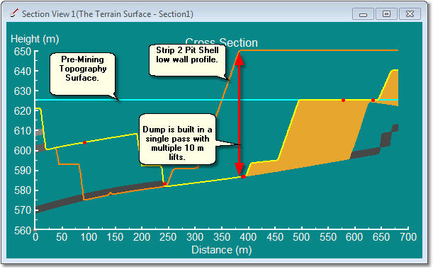
Strip 3 Low wall Dump Base Cross Section.
The Chione waste for Strip 3 reports to this dump. The geometry of this excavation means we can be confident that the reporting waste will fit within the dump below the level of the Pre-Mining topography surface. Ultimately another dump Strip 3 Low wall Top Dump will be constructed on top of this dump.
Out of Pit Dump.
The Ate and Boreas waste passes will generate a significant volume of material to be dumped. This material will report initially to the Strip 2 Low wall Dump Top. As material has already been dumped to the Strip 2 Low wall Dump base spoil room available above this level is limited and will most likely exceed the volume of the Ate and Boreas waste passes for Strip 4. As a consequence of this we require a second dump to include in the Dump Hierarchy to accommodate additional material which will not fit in the Strip 2 Low wall Dump Top.
The 3d-DigPlus file contains an Inner Surface called Out of Pit Dump 1, which has been designed using 3d-DigPlus's Dump Surface function. The following figures illustrate this dump surface and its location:
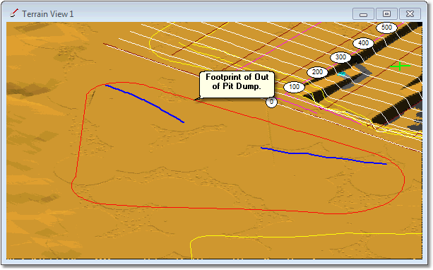
Footprint And Location of Out of Pit Dump.
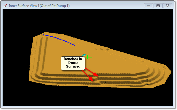
Out of Pit Dump Surface.
The Out of Pit Dump Surface is a benched landform. The benches have a vertical spacing of 10 m, and the first bench is at RL 625. This Dump will be built in 10 m lifts Using the Horizontal Benches option and a Set Level of 625. This will ensure that the dump levels matchup with the benches in the design surface.
The Dump Template for the Out of Pit Dump Surface will have the following characteristics:
•There will be two Pass Surfaces: Terrain Surface and Out of Pit Dump Surface 1.
•There is only a single pass resulting from the two Pass Surfaces and this pass will have multiple 10 m lifts, Horizontal Benches and a Set Level of RL 625.
•The Dump Direction for all lifts will be south to north.
•The dump Area Polygon will be placed just outside the Surface Feature for the footprint of the Out of Pit Dump Surface (see figure above).
The task required to complete this topic are:
1.Create a Dump Template for a Staged Dump for Strip 2 Low wall Dump Top. This Dump will be created by copying the settings and Dump Area from the existing Strip 2 Low wall Dump Base Dump Template. The new Dump Template created will have the correct Dump Area but the passes and lifts will require modification to conform with the requirements described above.
2.Create a Dump Template for a Staged Dump for the Strip 3 Low wall Dump Base. This Dump will be created by copying the settings from the Default Dump. As a result when created, the Dump will have no Dump Area. A dump Area is drawn along the Strip 3 low wall toe and extending around the area of the Strip 2 void. Passes will be set up to conform to characteristics described above.
3.Create a Dump Template for the Out of Pit Dump. This Dump will be created by copying the settings from the Default Dump. As a result when created, the Dump will have no Dump Area. A Dump Area will be drawn around the Surface Feature representing the footprint of the Out of Pit Dump Surface. A single pass will be set up with a characteristics described above.
The following Video Clip illustrates this procedure:
3d-DigPlus must be in Auto mode after the tutorial file is loaded:

Simulation Pulldown - Auto Mode
Load the File Topic9_Complete, when the exercise is complete save the 3d-DigPlus file under the name: Topic10_Complete.3dd
Topic10_Complete.3dd