|
<< Click to Display Table of Contents >> Staged Dumps |
  
|
|
<< Click to Display Table of Contents >> Staged Dumps |
|
Prerequisites for this Section
Before reading this section you should be familiar with Generic Dumping and Dump Templates (previous topics).
Staged to Dumping allows a dump to be built up in a series of passes and lifts. Is primarily used as part of Automated Excavation and Dump Sequencing, however it Is available in the Generic and Topographic Simulation module and can be used with the manual dumping process.
Staged Dumps will require an inner surface representing the final (as completed) surface of the Dump. Such surfaces may be generated by other software and imported as DXF file, or they can be created using the 3d-DigPlus Dump Surface utility.
Staged Dumps are typically used to model individual truck and shovel dumps. These include in-pit dumps such as low wall dumps as well is out of pit dumps. Staged Dumps are constructed as Area Dumps with a constraining surface. A typical staged dump will result in the construction of a benched landform with the shape and benching constructed to comply with various design criteria. 3d-DigPlus's Dump Surface Design function allows the user to create a benched landform from a given footprint conforming to various criteria. This results in the construction of a Inner Surface which can be used as a constraint for a staged dump. Alternatively dump surfaces designed in other systems can be imported as DXF files. Below are several examples of landforms created by Staged Dumps:

Staged dumps require for their functioning a design surface. This design surface represents the completed form of the dump. As the dump is progressively built, it is constrained the design surface along its outer edges. When the top of the dump reaches the top of the design surface, the dump is full. At the stage the form of the Terrain Surface and the dump surface will be identical in the region of the dump.
Setting up a staged dump requires that the design surface be nominated, the area to be dumped within identified and the mode of dump construction defined. Most dumps are not constructed to the full height of the constraining surface in a single operation. The waste material is placed in a series of discrete layers starting with the first layer placed at the base of the dump, and the final layer placed at the top of the dump. Each of these layers will be dumped starting at a particular end of the dump and progressing in a particular direction. The mode of dump construction is controlled by the manner in which these layers are placed, such layers can be defined in 3d-DigPlus via the use of Lifts and Passes.
A Lift consists of a layer of dumped material of uniform thickness (height). The shape of the bench surface forming the top of the lift can either be horizontal or defined by a surface. When bench surfaces are defined by surface, only one Inner Surface is required and the benches are created by offsetting this surface as the Lift parameters dictate. Frequently the dumps design surface will incorporate a system of benches around its perimeter, as can be seen in the dumps in the figure above. In such cases it is usual for the Lift benches to conform with the benches in the design surface, however it is not a strict requirement in 3d-DigPlus that the lifts conforming this manner.
A Pass in a Staged Dump involves the use of an Inner Surface to define an intermediate stage in the construction of the dump. Where Pass Surface is defined for a dump, the waste material for this Pass will have its own Lift parameters. The dump will be constructed from its base, in Lifts, to the first Pass Surface. At this intermediate stage the dump will be constrained by both the design surface and the Pass Surface. Following completion of the first Pass subsequent Passes will be constructed in the same manner until the dump is complete.
Before setting up a Staged Dump is important to carefully consider how the dump would be constructed and to decide what Lift parameters and Passes are required. Frequently only a single Pass will be required, the Pass from the base of the dump to the design surface. Passes provide additional flexibility and control over the Dump construction process. There are a number of situations in which Passes may be necessary, these include:
•Different dump directions for different stages of the dump.
•A requirement for the Dump to have a particular form part way through the construction process.
•Different Lift requirements for different levels within the dump.
Key information – Superimposed Dumps.
 Sometimes the use of Lifts and Passes is insufficient to provide the required flexibility in dump construction. An example is the case where an out of pit dump is shared by two different pits. In such cases each pit may have its own individual access and dump direction. This can result in particular lifts being constructed in different directions with material from each of the two pits. To handle this it is necessary to construct two dumps with a common dump area (footprint). these are referred to as Superimposed Dumps. Superimposed Dumps will share almost all characteristics in common except for dump direction. 3d-DigPlus makes the setup of these Superimposed Dumps easy as when used create a new Dump Template you have the option of copying to set up and the Dump Area from a pre-existing Dump Template. The procedure for creating Superimposed Dumps involves creating the initial dump, then creating the superimposed Dump copying all set up parameters from the pre-existing Dump. All it is required to complete the second Superimposed Dump is to change the dump direction for lifts.
Creating Staged Dumps involves creating a new Dump Template and setting it up for Staged dumping. This set up is conducted on the Staging page of the Excavation Template dialog:
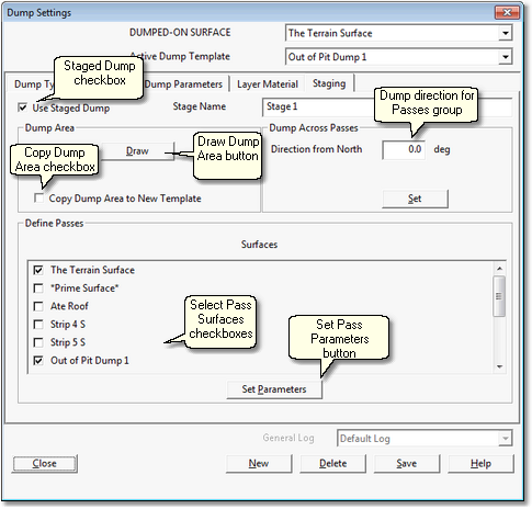
The Staging page has the following components and settings:
Staged Dump checkbox. Checking this box defines the dump for the current Template as a Stage Dump and enables all the relevant buttons and settings.
Draw Dump Area Button. Clicking this button temporarily dismisses the Excavation Template dialog and opens the Terrain Window with the Terrain Cursor active. The desired Dump Area is drawn on the topography. Before setting up a Excavation Template for a Stage Dump it is important to mark out in a terrain window the location of the dump's footprint. This is done by creating a Surface Feature. Typically when an Inner Surface exists for the dump design surface this will contain a Data Feature around the footprint. This Data Feature can be copied and pasted in a Terrain Window as a Surface Feature. When the Dump Area is drawn it is drawn around this footprint feature.
Copy Dump Area Checkbox. When a new Dump Template is created the user is presented with a list of all the existing Dump Templates from which to copy parameters for the new Dump Template. In the case of Staged Dumps the user has the option of copying that Dump Area polygon to the new template. When the Copy Dump Area checkbox is selected the Dump Area from the source Template is copied. This is useful when using Superimposed Dumps (see Key Information above). Unless you are creating a Superimposed Dump leave this box unchecked.
Dump Direction for Passes Group. This group allows the user to set the default dump direction for all Passes of all Lifts. Dump directions for individual Lifts can be subsequently modified. If you know the heading of the Dump Direction in degrees from North it can be entered into the direction field. Clicking the direction button temporarily dismisses the Excavation Settings dialog and opens the Terrain Window allowing the user to define the direction by point and click. Click anywhere in the Terrain Window then drag an arrow to define the direction. This direction will then apply to all Passes and all Lifts.
Select Pass Surfaces Checkboxes. All Inner Surfaces appear in this list with a checkbox. All Pass Surfaces for the Stage Dump are identified by the checkboxes. Most typically only the floor of the dump (the Terrain Surface, checked by default) and the dumps design surface are required.
Set (Pass) Parameters button. clicking this button opens the Pass Parameters dialog detailed below.
The parameters which control the Lifts for each Pass are set up in the Pass Parameters dialog:
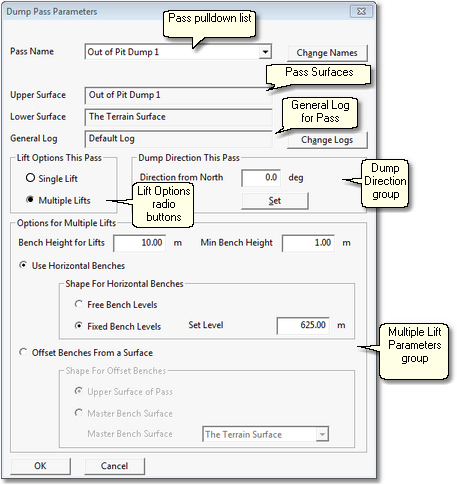
The Pass Parameters dialog has the following components and settings:
•Pass pulldown list. This pulldown list contains all passes created from the selected pass surfaces.
•Pass Surfaces fields. These are two fields which show the upper surface and lower surface for the currently selected Pass (the Pass that appears on a Pass pulldown list).
•General Log. Staged Dumps are most typically used as part of a simulation, in such cases this field is disabled as material reporting to the dump is determined by the Subsequence to which the Dump is assigned. If the Staged Dump is used in Free mode then the Log shown in this field is the one whose contents will report to the selected Stage Dump Lift. The Log can be changed by clicking the Set (Log) button.
•Lift Options radio buttons. These radio buttons allow the user to select between Single Lift and Multiple Lift options. If Single Lift is selected all material for the pass is dumped in one single lift. If Multiple Lifts is selected the material for the Pass is dumped in lifts according to the Options for Multiple Lifts.
•Options for Multiple Lifts group. This group contains all of the settings that control the characteristics of the Lifts when the Multiple Lifts option is selected. The settings are:
•Bench Heights for Lifts. This controls the height of individual lifts. It is the vertical distance between the bench surface onto which the Lift is dumped and the height of the bench surface formed by the Lift.
•Minimum Bench Height. The minimum bench height parameter is used to prevent the formation of very thin Lifts. Lifts with a thickness less than this amount will not be formed.
•Use Horizontal Benches radio button. When this button is selected the Lifts formed will be in the horizontal plane.
•Shape for Horizontal Benches group. Parameters in this group control benches when the Use Horizontal Benches option is selected. When Free Bench Levels is selected the system will determine the actual bench levels at each lift based on the above parameters. When Fixed Bench Levels is selected a Set Level is input into the Set Level field. Bench levels used in this case will be based on the Set Level in conjunction with the Bench Height for Lifts. In this case all bench levels will equal the Set Level plus multiple of the Bench Height for Lifts.
•Offset Benches from a Surface. When this option is selected all bench heights will be offset from the nominated surface. There are two sub options: Offset from Upper Surface of Pass and Offset from Master Bench Surface. When either option is selected the benches formed will have the same form as the nominated surface and will be offset based on the Bench Height for Lifts parameter and the Min Bench Height parameter. When the Upper Surface of Pass option is selected the Upper Surface of the current Pass will be used as the basis for Lift benches. When Master Bench Surface is selected an Inner Surface must be selected from the Master Bench Surface pulldown list. This Master Bench Surface will be used as the basis for the Lift benches.
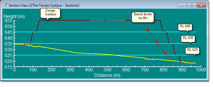
The Multiple bench Options are illustrated in the following figures.
Horizontal Benches Fixed Bench levels. In this example the Set Level is RL 625, this results in the benches matching the benches in the design surface:
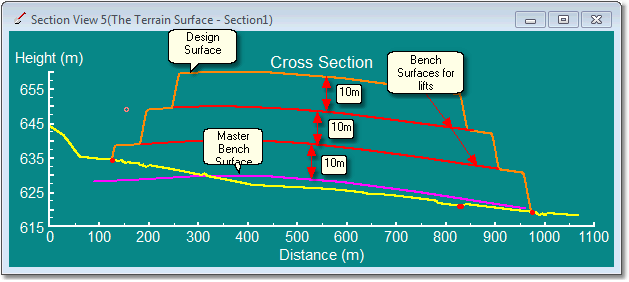
Offset Benches from a Surface. In this example the benches are created by offsets (10m) from a Master Bench Surfaces. Note that the Design surfaces also used this Master Surface so the Lifts coincide with Design Surfaces benches:
The following video clip shows the setup and operation of a staged dump with a single lift:
The following video clip shows the Dump featured above setup as a to Pass Dump. The setup for each Pass is similar apart from the Dump Direction which changes:
Key Information-Dump Speed
 When running large simulations a large proportion of the run-time is typically taken up in dump simulation. It is therefore desirable to set the dumps up to run as quickly as possible. There are several settings which can greatly increase dumps speed:
Dump Resolution. This is located on the Dump Parameters page of the Dump Settings dialog. This setting increases the spacing of the grid model used for dump simulation. When set to Very High the full Terrain Surface grid is used. As the setting is reduced so the grid spacing is increased. Increasing the spacing greatly increases dump speed at the cost of dump surface resolution. The resultant dump surface may look a bit "chunky". However, the volumetric accuracy will often be adequate at least for a first pass simulation. Usually there is some iteration required to design a good system of dumps. It is good practice to conduct the initial iterations with a low – fast dump setting, when the desired result is obtained the Supersequence can be rerun with high resolution to capture a quality slideshow and ensure full volumetric accuracy. Note that there is no fundamental volume error produced at low dump resolutions. However the dumps produced in this manner may not fully reflect the constraining design dump surface. The result can be that the volume contained in these low resolution dumps is a little lower than the actual volume under the design surface.
Discrete volume to Dump. This setting is also located on the Dump Parameters page of the Dump Settings dialog. A large volume will assist in running a large dump quickly. The default setting is 2000 BCM. 10,000 BCM may be more suitable for a large simulation.
Terrain Redraw Frequency. This setting is located on the Dump Type page of the Dump Settings dialog. As the dumping progresses the terrain is regularly updated to display the newly dumped material. This refresh takes a small amount of time but the cumulative effect over the course a large simulation can be significant. Reducing the Terrain Redraw Frequency can minimise this impost. However it is often desirable to have the terrain redraw frequently high during simulation in order to visualise dump progress.
Fast Draw. This setting is located in the main menu under Terrain/Fast Draw Settings. It contains a display option called Rarefied Grid. This setting works in a similar manner to the Dump Resolution, it thins the Terrain grid used for display in rendered Terrain Windows. As with the Dump Resolution using a rarefied grid results in a lower resolution of the rendered view. However it can greatly increase dump speeds and as discussed above you can use a low resolution to do the bulk of the iterative work, then set high resolution for final slideshow. Note that this setting does not affect volumetrics. Rarefied Grid will also speed up the time it takes to excavate.