|
<< Click to Display Table of Contents >> Dump Assignment for Complex Supersequences |
  
|
|
<< Click to Display Table of Contents >> Dump Assignment for Complex Supersequences |
|
Prerequisites
The material in this section requires an understanding of the topics covered in Automated Excavation Sequencing and Automated Dump Sequencing.
Most of the techniques required to assigned dumps for use in complex Supersequences have been covered in previous topics. The following topics cover several specialised techniques for use in dump assignments used with large multi strip Supersequence.
Based on the techniques described in previous topics when a dump is assigned to a Subsequence material will report to the dump as soon as the excavation of the Subsequence starts and if the dump has room available (i.e. all dump constraints are not yet met). This dumping will proceed to long as room is available in the dump. There are situations however when it is desirable to make a particular dump inactive until the excavation of the pit reaches a particular state. any particular state in the excavation of a pit can easily be defined by identifying the last Subsequence whose excavation finalises this state. The use of Subsequence dependency and dumps allows the dump to be set up so that it will not become active until the pit reaches a particular state.
The use of Subsequence dependency and dumps will be explained by the use of a model pit. This pit mines three seams Upper, Mid, and Lower seams. the following figures illustrate this pit:
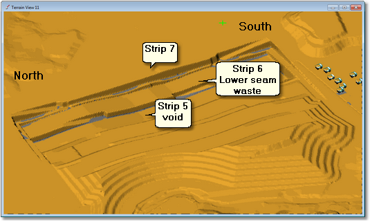
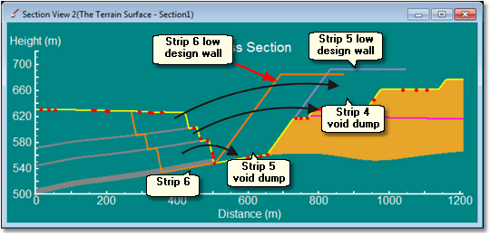
Cross section showing waste transport and dumps:
The excavation strategy for this pit involves no advanced stripping. Upper, mid and lower passes are excavated sequentially for each strip before moving on to the following strip.
Once a strip is complete the excavated void becomes available for dumping. In this example pit the design of each strip incorporates a low wall profile which contains a dump built on the floor of the previous strip.The cross-section above shows the three passes in strip 6, strip 5 void dump (constrained by the strip 6 spoil profile) and the strip 4 void dump (constrained by the strip 5 spoil profile). The dumping strategy calls for strip 6 lower seam waste to report to the base of the strip 5 void dump, and for strip 6 upper and mid seam waste to report to the strip 4 void dump. Note that when the upper and mid seam waste reports to the strip 4 void dump the strip 5 lower seam waste will have already been placed on the floor of this dump. This relationship between waste from particular strip and the dump to which it reports will apply to all strips in this pit. Dumps can be assigned to conform with this relationship using the following procedure:
•Create a Staged Dump for all void dumps for all strips.
•Lower seam waste Subsequences for strip n are assigned to the strip n-1 void dump.
•Upper and mid seam waste Subsequences for strip n are assigned to the strip n-2 void dump.
If all Subsequences have dumps assigned according to the above procedure, and the Supersequence is set up with no advanced stripping, all excavated material will report to a suitably available dump. However consider the situation where, having set up a Supersequence for and excavate option with no advanced stripping a second option where upper and mid seam passes are stripped in advance has to be modelled. Using the techniques described in previous topics rearranging the Supersequence to reflect this advanced stripping is a straightforward process. However if the Supersequence is arranged and the dump assignments as described above are used material from the advanced stripping will report to void dumps before the lower seam pass is complete. As an example consider the case where the upper seam pass is to be stripped two strips in advance of the lower pass, and the mid seam pass is to be stripped one strip in advance. The Supersequence for the upper seam pass in strip 8 will report to the strip 6 void dump. It is highly likely that the strip 6 lower pass will not be fully excavated at this stage. The use of Subsequence dependencies four dumps avoids this problem. In this example the void dump for every strip would have a Subsequence dependency to prevent material reporting to this dump for the void is clear.
Frequently Dumps will be required to accommodate waste from passes which are distant both vertically and horizontally. In such cases the dump access points, elevation of dumping and dump direction will vary for a Dump depending on the source of waste. The figure below shows an example:
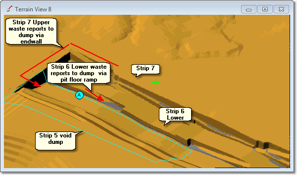
In the above example both the Strip 7 upper waste and the Strip 6 lower waste report to the Strip 5 void dump. However the Strip 6 waste is hauled down to pit floor and the dump is built in lifts from the floor level up. The Strip 7 waste is hauled to natural surface around the end wall and dumped off the end wall along a tip face from north to south.
To model the dumping of the Strip 6 waste the Dump Template must have the following Stage Dump settings:
The Staged Dump must have a single pass, the base of the pass is topography and the upper surface is the surface of the Strip 5 void dump surface. This pass is set up to dump with horizontal lifts at 10 m vertical spacing. The dump direction is north to south.
To model the dumping of the Strip 7 waste to Strip 5 void dump the 3d-DigPlus Dump Template must have the following Staged Dump settings:
The Stage Dump must have two passes, the first to model the initial tip face which starts at the end wall at natural surface level, and the second to build the dump up beyond this level in lifts. The first pass is from topography to a surface set up at the tip face level, and the second is from this surface to the final dump surface to be built up in lifts. The dump direction for both passes is north to south.
Clearly these two Dumps required Dump Templates with different characteristics. As a result a single 3d-DigPlus dump cannot be used for both dumps, and two Dump Templates are required. This situation where two 3d-DigPlus Dump Templates are required to model what is physically one dump is referred to as Superimposed Dumps.
Superimpose Dumps are set up via the following procedure:
•Create the first of the Superimpose Dumps, as this will be a Staged Dump this includes drawing the Dump Area.
•Create the second of the Superimpose Dumps, this time check the Create Superimpose Dump checkbox on the Staging page of the Dump Settings dialog:
•insert picture here
•Modify the Dump lifts and other settings as required and save.
Using this procedure 3d-DigPlus will create the second of the superimposed dumps with the same Dump Area as the initial dump. furthermore if the initial Dump Area is edited this changes reflected in both of the superimposed dumps.
The above description refers to the case of two Superimposed Dumps, however you can create any number of Superimposed Dumps.
In the Subsequence dependency topic above the example involved setting up dependencies to ensure no dumping occurs on active parts of the pit where stripping not complete. This is an absolute dependency, which ensures that non-feasible dumping does not occur.
Subsequence dependancies can also be used to give certain waste material priority access to a dump. Referring to figure (cross section) in the Subsequence dependency topic, the Strip 6 lower seam waste is to report to the nearby Strip 5 void dump. If the strip 6 lower waste is the first material to report to this dump, the haul will be short and the elevation minimal. However if material from another source reports to this dump before excavation of the Strip 6 lower waste, this will force the Strip 6 lower waste to be hauled higher when it is excavated.
Superimposed Dumps can be used in this situation to give priority to the Strip 6 lower waste. To do this two Superimposed Dumps are created. The first will be for the Strip 6 lower pass waste, and its Subsequence dependency will be set up to ensure that all Strip 5 waste is excavated before dumping can commence. The second Superimposed Dump will be based on this previous dump, but it's Subsequence dependency will use the Strip 6 lower pass waste final lift Subsequence or Subsequences. When Subsequences for other waste passes have the second Strip 5 Superimposed Dump assigned, they will also have a hierarchy of other dumps assigned, with Strip 5 Dump being the highest. If such waste is excavated prior to the Strip 6 lower waste, this material will skip the Strip 5 void dump and report to the next dump in the hierarchy.
The general use of Dump Limiting Surfaces was explained in the Creating Stage Dumps topic. A dump limit surface is typically used to ensure that the resultant dump conforms to a design. However a Dump which is set up with all constraints necessary to achieve the required dump design, can have an additional constraining surface applied to optionally limit the height or shape of the dump. In a typical strip mine the pit shell for each strip will incorporate a low wall profile designed to create the low wall void dump. The figure below shows a typical cross-section through a strip mine:
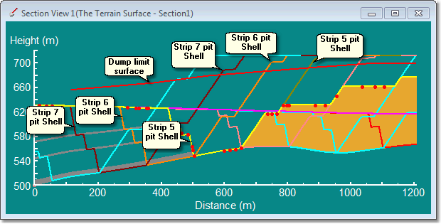
In the above figure shows the pit shell for several strips including the low wall profile forming the dump. The typical dumping strategy in such an operation will be to assign a dump hierarchy to Subsequences in strip n which has the highest priority dump as the strip n-1 void dump, followed by the strip n-2 void dump, and this hierarchy may continue to include many up-dip void dumps.
In a pit with dipping coal seams, as in the cross-section above, the initial strips are generally shallow and the adjacent void dumps are often not filled completely (to design) by these initial strips. As stripping progresses down dip and volumes increase adjacent void dumps become full and material then reports to void dumps further up-dip.
In the absence of any other constraints, the above strategy will sometimes lead to very high dumps in the latter half of the pits operation, and low dumps in the initial strips. This can result in excessively high haul, and an undesirable landform from a rehabilitation perspective.
A simple method for modifying such dumping is to start the design process by creating an overall dump limiting surface. Such surfaces may be designed in other systems and imported or can be designed in 3d-DigPlus using functionality such as Current Plane and Construct In a Surface. As each Stage Dump for the low wall Dumps are created they incorporate this limiting surface. In order to use such Limit Surfaces as part of the procedure to investigate a range of dump height options the following processes use:
1.Create a general Dump Limit Surface with the desired shape (topology) but ensure it is located well above all of the dump design surfaces.
2.Create all required Stage Dumps using the Limit by Surface option and selecting the above general Limit Surface.
3.Complete all necessary tasks to create a Supersequence with assigned dumps and run Simulation. As the general Limit Surface is well above all the dump design surfaces it will have no influence in this initial run.
4.Lower the general Limit Surface. This is achieved by opening up a Terrain Window to the surface, and setting up an excavation template where the inner polygon is bound to the Limit Surface but has a negative offset applied sufficient to depress the surface to a level below the Dump design. And Excavation Polygon is drawn to encompass the whole surface and excavation is performed which will depress the surface to a lower-level.
5.With the general Limit Surface now below the design Surfaces rerun the simulation.
6.Pit steps 4 and 6 as required. The general Limit Surface can also be raised if necessary using the excavation process.
The above procedure is covered in the tutorial exercise Using General Dump Limit Surfaces.
As well as the above use of general Limit Surfaces, specific Limit Surfaces can be used to modify the behaviour of individual Dumps such as out of pit Dumps.
The Dump Resolution has a major effect on the speed of Dumping Simulation, which is a major component of Simulation time. Reducing the Dump Resolution results in the system dumping material on a thinned version of the Terrain Grid. There is no loss in accuracy of reported Volumes however the dump is modelled at a lower resolution and this can result in a course appearance of the dump and less volume reporting to a given dump. Generally this volume reduction is small, but each case it should be assessed individually. When the Dump Resolution is reduced the Discreet Dump Volume should also be increased.
In the process of setting up a Simulation, doing a check Run of the Simulation and doing a Final run, all of the associated dumps will require different Dump Resolutions at different stages of the process. A low Dump Resolution will be used during the checking phase, and full resolution will generally be used for the final Simulation. The Dump Settings dialog has a Copy to button which allows the appropriate Resolution settings to be set in one Dump Template, and these settings then copied to a group of selected Templates. This makes the process of modifying the Dump Resolution settings across many templates quick and reliable. It is described in detail in the topic Copying Dump Parameters.