|
<< Click to Display Table of Contents >> Generating Dump Surfaces |
  
|
|
<< Click to Display Table of Contents >> Generating Dump Surfaces |
|
3d-Dig's Dump Surface command generates a benched landform to be used in a Staged Dump. These dump landforms are created prior to conducting a simulation and used to form dumps which will accommodate material during the simulation process. Note that landform models generated in other systems can be imported as DXF files and used for the same purpose.
The Dump Surface Function takes a user nominated dump footprint, plus benching criteria and generates a benched landform as a Inner Surface. This is generally used as a constraining surface when setting up a Staged Dump.
The command is initiated with the Terrain/Dump Surface command which opens the following dialog box:

Dump Surface Dialog.
The Terrain/Dump Surface dialog has the following components:
Bench Heights Group.
This group consists of two radio buttons; Flexible RL and Fixed RL. The benches are formed as either horizontal benches or as benches offset from a nominated Inner Surface. When the option Fixed RL option is selected the benches will be offset from the reference RL or surface by a fixed multiple of the Bench Spacing (vertical spacing) parameter. When the option Flexible RL is selected the first level will be determined using the topography around the footprint and the Max Bottom Bench Interval parameter.
Increasing the Max Bottom Bench Interval parameter relaxes the bench height parameter in the region where the dump surface merges with the topography. This effect is most easily described in the situation with the topography on which the bench is to be built is generally horizontal but where there is a localised hollow in the topography. If the Max Bottom Bench Interval parameter is set to the general bench interval additional benches will be added within the hollow and this will have the effect of creating an indentation in the dump surface reducing its volume. If the Max Bottom Bench Interval parameter is increased sufficiently a single bench with a larger batter will be added in the hollow preserving the form of the dump surface. The following figures illustrate this:

Dump Surface base topography and Footprint.

Dump Surface with Max Bottom Bench Interval set to general Bench Interval.

Dump Surface with relaxed Max Bottom Dump Interval.
Bench Parameters Group.
The Bench Parameters Group consists of the following elements:
Max Bottom Bench Interval. This is the parameter discussed above.
Max Top Bench Interval. This parameter applies to the final Bench added on top of the Dump Surface. It behaves in a similar manner to the Max Bottom Bench Interval parameter.
Maximum Dump RL. This parameter is and RL which limits the top of the Dump Surface. No benches will be added above this RL.
Bench Interval. This is the vertical spacing of the Benches.
Number of Benches. This is the maximum number of Benches to be included in the Dump Surface.
Bench Levels Group.
The parameters in this group control the Bench form. The Bench Levels parameters are:
Horizontal Levels radio button. When this option is selected all benches will be in a horizontal plane. The levels of the benches will be established using the Bind RL parameter and the Bench Interval parameter. All benches will be at an RL which is equal to the Bind RL plus an offset distance which is an integer multiple of the Pass Interval. Typically one bench will be at the Bind RL and the others will be offset using the Bench Interval.
Lift Planes radio button. When this option is selected all benches will be formed as inclined planes. The dip and dip direction of these inclined plane are set using the Bench Dip and Dip Direction parameters. Note that the fields for both these parameters include a Set button which starts an interactive tool allowing the user to create the direction of dip and the location of the dip point interactively on the topography. Setting these parameters creates a base plane and all Benches are then offset from this base plane using the Bench Interval parameter.
Lift Surfaces radio button. When this button is selected all Benches will be created as offsets from a nominated Inner Surface. This Inner Surface is selected using the Initial Bench Surface pulldown list. Bench Surfaces will then be created for each bench using this Initial Bench Surface and the Bench Interval parameter.
Bench Geometry Group. The Bench Geometry Group contains parameters which control the bench width and the batter angle between benches. The Bench Lifts parameter sets the typical width of benches. The Bench Angle parameter sets the typical batter angle between benches. The Number of Multiple Sections parameter allows portion of the dump surface as perimeter to have different bench geometry parameters applied. This parameter defaults to 0 in which case the Bench With an Bench Angle parameters apply to the entire perimeter of the Dump Surface. When the Multiple Angle/Width button is clicked the Terrain Cursor becomes active in the Terrain Window allowing the user to select portion of the Dump Footprint to be selected. This is the standard procedure for selecting portion of a feature or object and is demonstrated in the video clip at the end of this topic. Once a segment is selected a benched geometry dialog box is produced:
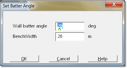
The desired parameters are keyed in and the OK button is clicked. At this stage the modified batters for the selected segment are registered and the Number of Multiple Sections field is updated. When the surfaces created the selected segment of the footprint will have the appropriate benched geometry applied and the remainder will have the base geometry applied. The following figure illustrates this:

Dump Surface with Multiple Bench Geometry.
Footprint Group. The Footprint Group consists of two buttons which allow the selection or creation of a Footprint Feature. The Select Footprint button allows the user to select a pre-existing Surface Feature to act as the Dump Footprint. When this button is selected the terrain window becomes active and the user can select the desired Feature. Note that only Features with the Closed status are eligible candidates for selection. If the desired feature is not Closed, exit the command, select the Feature then use the Terrain/Features/Customise command to set the feature status to Closed. The the Draw Feature button allows the user to draw a Closed Surface Feature to act as the Dump Footprint. When this button is selected the terrain window becomes active in the user can draw the feature in the usual manner.
Save Intermediate Dump Surfaces checkbox. When this box is selected, and the Dump Surface is generated, an Inner Surface will be generated for each bench. This surface will extend to the extents of the dump footprint and is contiguous within this footprint. These surfaces can be useful when doing Staged Dumps.
Generate Dump Surface button. When the setup is complete the Generate Dump Surface button is selected and the dump surface is generated.
The following video clip illustrates the creation of a Dump Surface: