|
<< Click to Display Table of Contents >> Surface/Data Feature Functions |
  
|
|
<< Click to Display Table of Contents >> Surface/Data Feature Functions |
  
|
3d-DigPlus incorporates a range of functionality for the creation and modification of Surface Features and Data Features. There are two distinct sets of functions for this purpose:
•Terrain/Features functions. These functions are access via the menu item Terrain/Features. They allow for manipulation of pre-existing Features.
•Direct Feature edit. Features which appear in any window can be directly selected and modified.
These functions are accessed via the main menu command Terrain/Features. This produces the Features submenu:
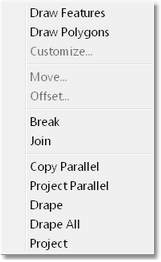
Feature Edit Menu.
These commands collectively apply to both Surface and Data Features.
Surface Features are line strings which appear in a solid rendered view of a surface. They are two-dimensional and appear draped on the surface.
Data Features a three-dimensional line strings which form part of the raw data from which the surface model is produced. They appear in a Data Window for a surface.
Some of the Feature functions are applicable to both feature types, and some to only Data Features. Hence some of the Feature Edit sub menu items will appear disabled depending on the type of active window at the time.
 Tip - Fast Draw mode and Feature selectability
When performing pan, rotate and zoom functions within a window the contents are presented in Fast Draw mode. If a Windows' contents are drawn in Fast Draw mode they will not be accessible when performing various functions. The window must be refreshed (using the toolbar refresh button) to restore it to a usable form. If the contents of the active window are in Fast Draw mode then the Feature menu options described here will be disabled. With most window types it is obvious on inspection that they are in fast draw mode. However with Data window types it may not be so clear. If the Feature menu items appear disabled go back to the active window and refresh.
Note that both feature types can have the form of an open line string or a closed polygon.
Applies to: Surface Features and Data Features.
The Draw Features command allows the user to create a new feature buy interactively drawing in a window. When the command was initiated focus moves to the active window (the window which was active at the time the command was initiated). The cursor is moved to location of the start of the desired feature and a left mouse click places the first feature vertex at this point. Remainder of the feature is placed interactively, when all Feature vertices are placed a right click completes the Feature. the window will remain in the Add Feature mode allowing additional Features to be created. When all Features are created right click a second time to terminate the command.
When this command is applied either a Data Feature or a Surface Feature will be created depending on the type of active window. if the active window is a Data window a Data feature will be created. If the active window is a window displaying a rendered or framed surface, a Surface Feature will be created.
If a Data Window is active and therefore a Data Feature is created, on placement of the first vertex the Set Vertex Height dialog will be produced:
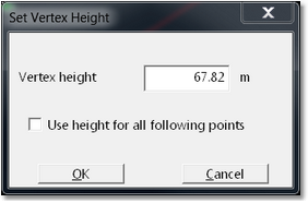
Set Vertex Height dialog.
Moving the cursor to the desired start point for the Feature locates the initial vertex in easting and northing, however and RL must also be specified. The Set Vertex Height dialog box allows the user to specify the RL of the vertex by keying the number into the Vertex Height field. The Set Vertex Height dialog includes checkbox titled "Use height for all following points". If this checkbox is selected the RL initially specified will be applied to all subsequent points in the Feature. If this checkbox is not selected the Set Vertex Height dialog will be produced each time a new vertex is added.
When all vertices in the Data Feature have been added right click to complete the Feature.
Applies to: Surface Features and Data Features.
This command is the same as Draw Features with the exception that the first and last vertex in the completed feature are joined to produce a closed polygon.
Applies to: Surface Features and Data Features.
This function allows the characteristics of the selected Feature or group of Features to be modified. At least one Feature needs to be selected in order to this command to be enabled. Note that this command can also be accessed by pointing to any feature and right clicking, this will produce a pop-up menu which includes the option Customise.
When this command was initiated the Customise Feature dialog is produced:
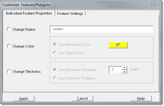
Customise Feature dialog.
The first page of the Customise Feature dialog is the Individual Feature Properties page and includes the following items:
Change Name checkbox and field. If the Change Name checkbox is selected the adjacent field becomes active allowing the user to key in a unique name for the feature or group of features selected.
Change Colour Group. This group consists of the Change Colour checkbox and colour selector items. When the Change Colour checkbox is selected the user has the option of Use Individual Colour which allows selection of the unique colour for the selected feature or group of features. This colour is selected via the Colour Selector tool provided.
A second option for colour is Use Type's Colour. Features in 3d-DigPlus can be classified by three feature types: Crest, Toe and Other. These feature types have no functional significance, they are supplied to assist the user in organising Features. Default colours are provided for these types and if the option Use Type's Colour is selected the features will take on the default colour for that type. the type colour can be modified via the Terrain Window Appearance dialog.
Change Thickness Group. This group is similar to the Change Colour group described above with the exception that it controls the thickness (line weight) 4 to selected feature or group of features.
The Features Settings dialog includes the Features Settings page:
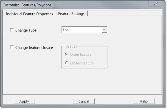
Customise Feature dialog, Feature Settings page.
The Feature Settings page includes the following items:
Change Type checkbox and pulldown list. when the Change Type checkbox is selected the user can change the type of the selected feature or group of features by selecting a new type from the adjacent pulldown list.
Change Feature Closure group. When the Change Feature Closure checkbox is selected the user can use the adjacent radio buttons to select from the option Open feature and Closed feature. An open feature is one which consists of a line string, a closed feature is a feature which forms a closed polygon. When the Close Feature option is applied to Feature which is initially a line string, the two end vertices will be joined to form a polygon. in order for this operation to be valid the feature form must be such that it can be closed without producing feature elements which cross.
Applies to: Surface Features and Data Features.
Feature must be selected before this command is initiated. When this command is initiated the Feature Move dialog is produced:
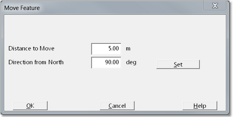
Feature Move dialog.
In the Feature Move dialog the distance to movie specified in the direction from North. The direction can either be keyed in or set interactively using the Set button. When the OK button is clicked the feature is moved by the specified distance in the specified direction.
Applies to: Surface Features and Data Features.
This command is similar to the Features Move command, with the difference that the original feature is maintained and a copy of this feature is placed at the new location.
Applies to: Surface Features and Data Features.
The Features Break command breaks a single feature into two features at a point nominated by the user. The procedure for breaking a Feature is as follows:
Make sure the feature, and a break point, are clearly visible in the active window.
Select Terrain/Features/Break. The Terrain Cursor will become active in the Terrain Window. Move the Terrain Cursor on top of the target feature and left click.
The Terrain Cursor will snap to the Feature and respond to SIDEWAYS mouse movement. Move the cursor to the desired breakpoint and left click. The feature will be broken into two features at the nominated breakpoint.
The following video clip illustrates the Feature Brake command:
Applies to: Surface Features and Data Features.
The Terrain Features Join command joins to Features to form a single Feature. The procedure for joining to Features is as follows:
Make sure the features, and their relevant endpoints, are clearly visible in the active Terrain Window.
Select the Terrain/Features/Join command. The Terrain Cursor will become active in the Terrain Window. The Terrain Cursor in this mode will have limited movement, it can only be located at candidate feature endpoints. As the mouse is moved the Terrain Cursor will snap to the nearest Feature endpoints.
Move the cursor to the first Feature endpoint and left click, then move to the next Feature endpoint and left click. The two features will now be joined.
The following video clip illustrates the Terrain Features Joint command:
Applies to: Surface Features and Data Features.
The Terrain Copy Parallel command copies a selected portion of a Feature, in a specified direction by a specified distance. Note that the feature is copied parallel to the original feature so the direction specification is limited, the Feature can be coped to one side or the opposite side of the source Feature. The procedure for copying a Feature parallel is as follows:
Ensure that the target feature is clearly visible in the active Terrain Window. This command will put the active Terrain Window into plan view mode. It is best to manually put the window into plan view mode prior to initiating the command to ensure that the appropriate section of the feature remains visible in plan view mode.
From the main menu select Terrain/Features/Copy Parallel. When the Terrain Cursor will be active in the Terrain Window. Move the Terrain Cursor on top of the target Feature and left click.
The Terrain Cursor will now be snapped to the target Feature and will move along the Feature in response to SIDEWAYS mouse movement. The portion of the target Feature which is to be copied must now be marked. move the Cursor to the start point on the Feature and left click. As the mouse and cursor are subsequently moved the portion of the Feature to be copied will be highlighted. Move the cursor to the end of the relevant portion and left click. If the entire feature is to be copied start by moving the cursor to one end and left clicking, then move to the opposite end and left click.
The Terrain Cursor will now disengage from the Feature. As the cursor is moved either side of the Feature direction arrows will appear. Move the Cursor so the direction arrows point in the correct direction and left click. the Copy Parallel dialog will be produced:
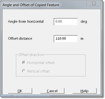
Features Copy Parallel dialog.
The fields in the Features Copy Parallel dialog which are enabled will vary depending on whether a Surface Feature or a Data Feature are being copied. In the case of a Surface Feature only the Offset Distance field is enabled. This parameter defines the distance by which the new Feature will be offset from the source Feature.
In the case of Data Features the feature can be copied up and down as well is horizontally. This movement is specified via the Angle from horizontal parameter. The offset distance can be specified as either a a horizontal offset or a vertical offset, this is set via the Offset direction radio buttons. If for example the angle from horizontal specified is 20°, the offset distance is 100 m and the offset direction is horizontal offset then the horizontal distance between the source Feature and the new Feature will be 100 m. The angle subtended between a line joining two equivalent points on the to features, and a horizontal plane will be 20°. This is illustrated in cross-section in the following diagram:
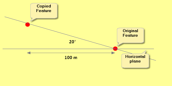
Features Copy Parallel.
When the setup is complete the OK button is clicked and the new Feature will be created.
The following video clip illustrates the Features Copy Parallel command:
Applies to: Surface Features and Data Features.
The Project Parallel command is similar to the Copy Parallel command. The Copy Parallel command does not alter the form of the source Feature when copying. The copy Feature has an identical form to the original but is in a different location. The Project Parallel command however projects each straight line segment of the source feature in a direction perpendicular to the source straight line segment, by the specified distance. The following diagrams illustrate this. Here two Features have been created from the same source feature with an offset distance of 30 m, one by Copy Parallel and the other by Project Parallel.:
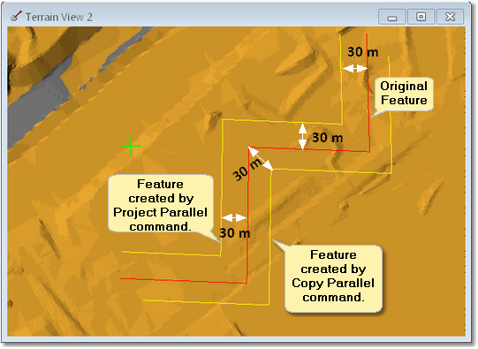
Feature copy and Feature project.
Applies to: Data Features only.
The Feature Drape function takes a selected portion of a selected Feature and projects it vertically onto a nominated surface. Depending on whether the nominated surface is above or below the selected Feature, the selected Feature is moved up and down as required to drag it on the nominated surface. The following figure illustrates this function:
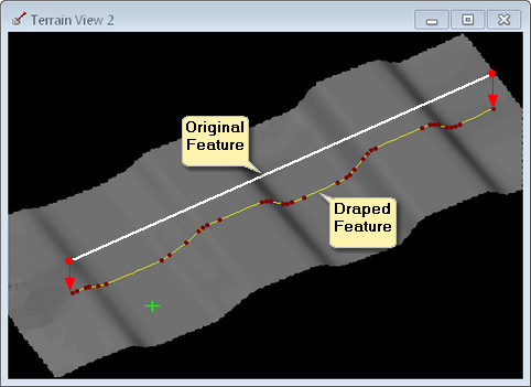
Feature Drape function.
In the above figure the original Feature is at all points above the drape to surface. Hence the feature is projected down onto this surface. If the original Feature was at all points below the draped to surface it would be projected upward, and if it interleaves the draped to surface portions will be projected up-and-down as required.
Before initiating this command there must be a Data Window open to the surface containing the Feature to be draped. As the Drape command will put this window into plan view mode it is best to manually put the window into plan view mode first to ensure that all of the feature is visible. The procedure for draping a Data Feature is as follows:
When the Terrain/Features/Drape command is initiated the Terrain Cursor will become active in the terrain window. Move the cursor on top of the desired Feature and left click. the Cursor will now snap to the feature and respond to SIDEWAYS mouse movements. Move the cursor to the starting point of the desired section of the Feature and left click. As the cursor is subsequently moved the portion of the Feature to be dragged will be highlighted, select the desired portion and left click again.
the Drape Settings dialog will be produced:
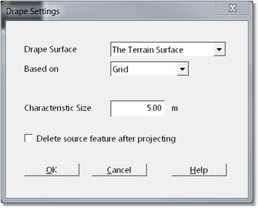
Drape Settings dialog.
At the top of the Drape Settings dialog is a pulldown list titled Drape Surface. This pulldown contains a list of every surface in the 3d-DigPlus file. The surface to which the selected Feature portion is to be draped is selected from this list. There is a pulldown list titled Based on. This list has two options Grid and Triangulation, it determines which surface model is to be used in the draped process. In most instances the best model to use is Grid. Towards the bottom of the dialog is the checkbox titled Delete source feature after projecting. It is commonly the case that the source Feature for drape is a feature that has been acquired from elsewhere, often copied from the topography and pasted into the data window. In such cases the source Feature has the correct planar coordinates but has to be draped to acquire the correct elevation. In this case the source feature must be deleted and replaced by the draped feature. selecting Delete source feature after projecting will ensure that the source feature is deleted after the draping process.
Once all of the settings are input click be OK button and the feature will be draped.
Applies to: Data Features only.
The Feature/Drape All function is very similar to the Drape function. However the Drape All function only allows selection of a complete Feature (as opposed to a segment of the feature) and the entire Feature is subject to draping.
Applies to: Data Features only.
The Feature/Project function takes a selected portion of a selected Feature and projects it at a nominated angle, in a nominated direction, and moves it as necessary to project it onto a nominated surface. It is similar to Drape with the exception that a projection angle can be specified. Whereas the Drape function only moves the feature vertically,the Project function can move it at a nominated angle. The following figure illustrates this function:
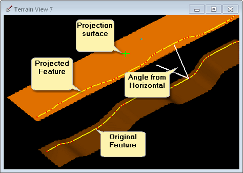
Feature Project function.
In the above figure the nominated Projection surface is at all points above the level of the source Feature. In this case a positive projection angle would be specified. If the Projection surface is below the source Feature a negative projection angle is specified. Note that this function will only create a projected Feature where it is feasible to do so. If in the above example a negative projection angle had been specified this would imply that the source feature must be moved downwards in the projection process. As the Project surface is at all points above the source Feature no projection is possible and no projected feature would be produced. If the Projection surface interleaves the source Feature (in elevation) a number of projected features will be produced in those areas where projection is feasible, no features will be present in those areas where projection is not feasible.
Before initiating this command there must be a Data Window open to the surface containing the Feature to be projected. As the Project command will put this window into plan view mode it is best to manually put the window into plan view mode first to ensure that all of the feature is visible. The procedure for projecting a Data Feature is as follows:
When the Terrain/Features/Project command is initiated the Terrain Cursor will become active in the terrain window. Move the cursor on top of the desired Feature and left click. the Cursor will now snap to the feature and respond to SIDEWAYS mouse movements. Move the cursor to the starting point of the desired section of the Feature and left click. As the cursor is subsequently moved the portion of the Feature to be dragged will be highlighted, select the desired portion and left click again. At this stage the direction tool will be produced, as the mouse cursor is moved either side of the source Feature direction arrows will be produced (See Features/Copy Parallel video clip above). Drag the direction arrows to indicate the desired project direction and left click.
The Projection Settings dialog will be produced:
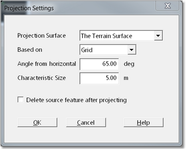
Feature Project dialog.
At the top of the Projection Settings dialog is a pulldown list titled Projection Surface. This pulldown contains a list of every surface in the 3d-DigPlus file. The surface to which the selected Feature portion is to be projected is selected from this list. There is a pulldown list titled Based on. This list has two options Grid and Triangulation, it determines which surface model is to be used in the project process. In most instances the best model to use is Grid.
The field titled Angle from horizontal allows the input of the projection angle. Note that a positive angle will project a feature upwards from horizontal, and a negative angle will project downwards. As discussed above Projected features will only be created if the source Feature projected in the nominated direction at the nominated angle intersects the Projection surface.
Towards the bottom of the dialog is the checkbox titled Delete source feature after projecting. If this checkbox is selected the source Feature will be deleted after the projection process.
 Warning - use of delete source feature.
Both the Feature Drape and Feature Project dialogs have the option to delete source feature after projecting. Typically this option is required when draping but not when projecting. 3d-DigPlus remembers the setting between these two commands. It is very important when applying the Project command to ensure that the Delete source feature checkbox is not checked if you wish to retain the source feature. It is easy to ignore this point and inadvertently delete the source feature, which must then be replaced. If this does occur use the undo button to restore the source feature then repeat the projection process with Delete source feature deselected.
Once all appropriate parameters and settings are important click the OK but and to project the feature.
Surface and Data features can be edited by direct manipulation within a window. Both types of Features can be manipulated via the tools described in the topic Manipulating Vector Objects.
Data Features have an additional facility to edit individual vertex elevation. Selecting a Feature then pointing to a vertex and right clicking will produce the Edit Feature pop-up menu. When this function as applied to Data Feature the menu includes the option Change Elevation. Selecting this option produces the Change Elevation dialog. This contains a single field which displays the current vertex elevation. This field is editable and an alternative elevation can be entered.