|
<< Click to Display Table of Contents >> Cross & Longitudinal Sections |
  
|
|
<< Click to Display Table of Contents >> Cross & Longitudinal Sections |
|
3d-DigPlus allows for the placement of cross sections (two point straight line section) and longitudinal sections (multiple point section line). When these sections are used to visualise the terrain and inner surfaces and are also utilised by number of functions which provide the construction of specialised Inner Surfaces.
The cross-section function allows the user to create a two point section feature which is subsequently used to produce a cross section view in a cross section window.
The following procedure is used to create a new cross-section:
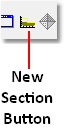
From the Toolbar click on the New Section toolbar button:
The Terrain Cursor will become active in the Terrain Window. The cursor is moved to the start point for the new section and let clicking anchors the new section at this point. The cursor is then moved to the opposite end of the new section and a left click complete the process. Section Window display in the cross-section will be automatically generated. The following figure illustrates a typical section window:

Section Window.
The cross section window contains the following elements:
Surface Names List. The surface names list is a list of all surfaces currently displayed in the section window.
Layer Names List. The layer names list is a list of all layers currently displayed in the section window.
Topography. The topography is a trace line, in the section window, representing the Terrain Surface. Its default colour is yellow which distinguishes it from all other surfaces.
Inner Surfaces. The In a Surface trace lines represent each Inner Surface displayed in the cross-section. These trace lines Have the default colour of light blue. Inner Surface trace lines can be individually coloured using the Terrain/Surfaces/Edit command. This brings up a dialog box which allows access to the Trace Colour selector.
Layers. All Layer is selected for display in the Cross Section appear solid rendered between their roof and floor surfaces. The colour of these Layers is the colour selected when the layer is originally created.
Reference Point. When the cursor is moved over a Section Window it becomes active in the window. The easting, northing and RL of the cursor location are displayed in the 3d-DigPlus window status bar.The distance and angle from the Reference Point to the current cursor location are also displayed. To reset the Reference Point to a new location move the cursor to that location and either left or right click.
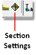
To modify the appearance and settings for a Cross Section window make the window active and click on the Sections Settings toolbar button:

This opens up the Section Settings dialog. The section settings dialog contains four pages which control the appearance of the section window.
Section Settings General Page.
The section settings general page is shown in the figure below:

Section Settings General Page.
The section settings general page contains the following elements:
Section Number pulldown list. This list contains all sections in the current 3d-DigPlus file. The default section contained in this list is that for the active section window at the time the Section Settings command was initiated. If a section window for a different cross-section is required, the relevant cross-section is selected from the list and New Window button at the bottom of this dialog is clicked. This will produce a new section window displaying the selected Section.
Section View Name. A particular section can optionally be given a unique name via this field and this name will appear at the top of the section window.
Height Range Selection group. The Height Range is the range of elevation covered by the section window. There are two options for determining this range, Automatic and Manual. The default is Automatic where 3d-DigPlus determines the lowest and highest elevations of all surfaces within the section and these elevations are used for the minimum height and maximum height displayed within the section. This default is intended to ensure that all parts of all surfaces are displayed within the cross-section. The Manual option allows the user to enter values into the Minimum Height and Maximum Height fields. These manually nominated elevations are then used to establish the elevation range for the section.
Height Scaling Group. There are two options for Height Scaling, Fit to Window and Proportional. The Fit to Window option stretches the section vertically to fit within the size of the Section Window. The Proportional option size is the vertical span of data within the Section Window so that the vertical and horizontal scales are equal (i.e. there is no vertical exaggeration).
Show Surface Features checkbox. When this box is checked a market is placed in the cross-section, on the topography trace, wherever the section crosses Surface Feature.
Surface Section Based on pulldown list. This pulldown list determines which model (grid or triangulation) will be used for the display of the terrain surface in cross-section. Where a terrain surface has both a grid model and triangulation the user can optionally select either model for display in cross-section. As the grid model is the only model used for simulation this option should generally be left at the default setting of Grid.
Section Line Width. This is the line width for the trace line representing the topography in the cross-section.
Section Line Colour. This is the colour for the trace line representing the topography in the cross-section.
Background Colour. This is the background colour for the cross-section.
Section Settings Inner Surfaces page.
The Section Settings Inner Surfaces page is shown in the figure below:

Section Settings Inner Surfaces Page.
The Section Settings Inner Surfaces page contains the following elements:
Show In a Surface Traces checkbox. This checkbox controls whether or not inner surfaces appear in the cross-section window. It defaults to selected which results in inner surfaces being displayed in the section window. If inner surfaces are not required in the section window this checkbox can be deselected.
Clip to Section Surface checkbox. Inner Surfaces will often extend above the topography. This may be due to the geological model predating the current strip, or due to a design surface which necessarily extend above the topography. When the Clip to Section Surface checkbox is selected only those parts of inner surfaces which are below topography are displayed.
Inner Surface Sections Based on pulldown list. Where both grid and triangulation models exist for an Inner Surface either model may be used to display the surface in cross-section. The Inner Surface Sections Based on pulldown list allows the user to select which model will be used. Note that if a particular surface does not have the model type selected its trace final be generated using the model which exist for that surface.
Show Inner Surface Names checkbox. This checkbox determines whether or not Inner Surface names appear in the section window.
Number Surfaces checkbox. This checkbox determines whether surfaces are numbered in the section window.
Inner Surface Trace Width. This parameter controls the line with of Inner Surface trace lines in the section window.
Surfaces to Show list. This list contains all Inner Surfaces with individual checkboxes. It allows users to select a subset of Inner Surfaces to display in the section window. Frequently only a small subset of all Inner Surfaces are relevant to a particular task and removing the unnecessary Inner Surfaces makes the section window more legible.
Section Settings Layers page.
The Section Settings Layers page is shown in the figure below:

Section Settings Layers Page.
The Section Settings Layers page contains the following elements:
Show Layers checkbox. This checkbox determines whether or not layers appear in the section window.
Clip to Section Surface checkbox. Layers will sometimes extend above the topography, Selecting this option will clip all parts of layers which are above the topography.
Show Layer Names checkbox. This checkbox determines whether layer names appear in the section window.
Number Layers checkbox. This checkbox determines whether layers are numbered in the section window.
Layers to Show. This is a list of all Layers in the 3d-DigPlus file together with the checkbox for each layer. it allows the user to select a subset of all layers to display in the section window.
Section Settings Axes Page.
The Section Settings Axes page is shown in the figure below:

Section Settings Axes Page.
The section settings axes page contains the following elements:
Axes Width field. This field controls the line width of the section axes.
Axes colour selector. This colour selector controls the colour of the section axes.
Show Minors checkbox. When this checkbox is selected minor axes are displayed.
Show Grid checkbox. When this checkbox is selected gridlines placed on the section along the major axes.
Grid with field. This field controls the line width of the Grid.
Grid Colour Selector. Is selected controls the colour of the grid.
Existing cross sections can be modified when using the methods described in the topic Manipulating Vector Objects. These methods allow a section line to be moved and stretched. Once the modifications have been made the cross-section can be updated by making active it's section window then clicking the refresh button in the View group on the main Toolbar:
Refresh Toolbar Button.
On occasions a section window may get deleted. When such a window is deleted the original parent cross-section remains on the topography. To create a new Section Window for an existing cross-section use the following procedure:
Click on the Sections Setting toolbar button:
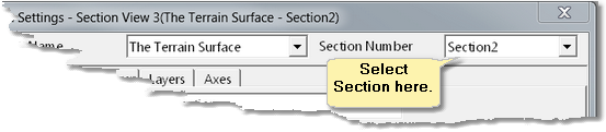
In the Section Settings dialog box select the required Section from the Section Number pulldown list at the top right:
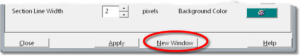
Finally at the bottom of the Section Settings dialog click the New Window button to open a new Section Window:
The Longitudinal Sections function is accessed from the Main Menu item Utilities/New Longitudinal Section. When this command is accessed the Terrain Cursor becomes active in the Terrain Window. A multi-segment section feature is placed by point and click. When the final point in the section is placed are right mouse click is used to complete the section line. When the section line is complete section window is automatically generated.
In all other respects the Longitudinal Sections function, and its various settings, are identical to those for Cross Sections. All relevant section window settings are accessed via the Section Settings toolbar button described above.