|
<< Click to Display Table of Contents >> Dragline Bench Design |
  
|
|
<< Click to Display Table of Contents >> Dragline Bench Design |
  
|
The dragline bench design utility allows the user to create a surface to model a proposed dragline bench. The bench is created to conform to various design criteria. The bench design is conducted prior to conducting the dragline simulation for a strip. The resulting bench Surface can then be used as a constraining surface to progressively build the bench during simulation.
Designing a dragline bench with this utility involves the following steps:
1.Inputting relevant bench design criteria.
2.Designing the bench profile along the length of the strip.
Step 1 is achieved by inputting the criteria into the Bench Design dialog, and identifying design Surface Features.
Step 2 is conducted by interactively drawing the profile in a longitudinal section running along the bench centreline.
Once the steps are completed 3d-DigPlus automatically generates the Bench Surface.
The figure below illustrates the dragline bench parameters:
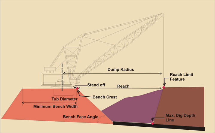
Definitions of Dragline Bench Parameters.
The Dragline Bench parameters are:
•Dump radius. The draglines' dump radius measured from the centre of rotation to the radius at boom tip.
•Tub diameter. This is the diameter of the draglines' tub.
•Stand-off. The minimum allowable distance between the outer edge of the tub and the crest of the bench.
•Minimum bench width. The minimum allowable width of a workable dragline bench.
•Bench face angle. The angle of the face of the dragline bench measured to the horizontal.
•Reach. The distance between the crest of the Dragline Bench to the most distant point that the dragline can reach to commence digging. Reach= Dump radius -Stand-off -( tub diameter)/2.
•Reach limit feature. A 3d-DigPlus Surface Feature which defines the most distant point in the overburden that the dragline must reach in order to excavate the strip. The user must provide or draw this Feature.
•Maximum dig depth line. This is a 3d-DigPlus Surface Feature which is located along the line of the deepest part of the excavation. In a typical pit this is the highwall toe. The user must provide or draw this Feature. The Bench Design Utility assists the user when drawing the bench profile by displaying a line in the Longitudinal Section indicating the height of the Maximum Dig Depth. The Bench profile cannot be placed higher than this limit without exceeding the draglines dig depth limits. In order to establish this height the system needs to know the deepest part of the excavation over the length of the strip. It is assumed that the dragline will be uncovering a coal seam. Therefore this point of maximum excavation depth will occur on a coal roof surface. The appropriate coal roof is selected using the Coal Roof pulldown list. The location on the coal roof of the deepest point of excavation is determined by identifying a Surface Feature. In a pit with a normally dipping seam, the line of deepest excavation is along the highwall toe. Using the Select Toe button the appropriate Surface Feature is identified. If the pit does not have a normally dipping seam, and the point of maximum depth is not the highwall toe, then an alternative feature running along the line of maximum depth should be selected.
The dragline Bench utility allows the user to interactively design a bench which conforms to the above parameters and criteria. The form of the resultant bench is shown in the figure below:
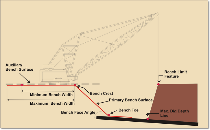
3d-Dig Dragline Bench Surfaces.
Once all criteria are input and the user defines the profile of the top of the bench along the strip, 3d-DigPlus generates two Bench Surfaces:
•Primary Bench Surface.
•Auxiliary Bench Surface (This Surface is named the Bench Roof).
The Primary Bench Surface includes the top of bench, which extends from the bench crest line up dip for a distance equal to the Maximum Bench Width. On the down dip side the bench crest line is projected down to the top of coal at the Bench Face Angle. This projection produces the Bench Toe as shown on the figure above. The Primary Bench Surface is then projected 50 m further down dip at coal roof level .
The Auxiliary Bench Surface is located at the level of the top of the Primary Bench Surface. This surface is horizontal in cross section and projects beyond both the Bench Crest and the minimum bench width limit.
During Dragline Simulation part of the operation involves excavating material, usually along the highwall, and dumping this material to form the bench. The Primary Bench Surface is typically used as a dump constraint for this purpose. However, situations frequently arise where dumping must extend beyond this Primary Bench Surface. If material excavated from the highwall has more volume than that required to form the bench, the excess can either be dumped to they are used in the civil arouspoil or used to extend the bench further up dip. In the latter situation the Auxiliary Bench Surface can be used for this purpose. Other situations, such as manoeuvering when crossing a ramp, may involve extending the intermediate bench beyond the Primary Bench Surface in either direction. Again the Auxiliary Bench Surface can be used for this purpose.
The dragline Bench Profile is created interactively in a section window. Consequently a Longitudinal Section is required running approximately along the centreline of the proposed Bench. Before starting the Bench Design procedure a Longitudinal Section must be created. This section is created using the Main Menu option Utilities/Longitudinal Section. This section should start at the end wall slightly beyond the commencement point of the proposed bench and terminate at the opposite end wall in a similar manner.
The procedure for creating a Dragline Bench involves firstly setting up all appropriate parameters in the Dragline Bench Design dialog, and finally selecting the Draw Bench button and drawing the Dragline Bench profile in a section window. The video clip at the end of this topic demonstrates the complete procedure for designing a dragline bench.
The Dragline Bench Design utility is accessed via the Main Menu Utilities/Dragline Bench Design. This brings up the Dragline Bench Design dialog:
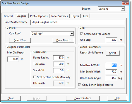
Dragline Bench Design Dialog.
At the top of the Dragline Bench Design dialog is the Section pulldown list. This list contains all Cross-Sections and Longitudinal Sections in the 3d-DigPlus file. The Bench profile is drawn in a Longitudinal Section and the appropriate Section must be selected using the Section pulldown list.
The Dragline Bench Design dialog contains six pages. Only two of these pages, Dragline and Profile Options, are specific to the Dragline Bench design. As the bench profile is drawn in a Longitudinal Section, the appropriate Section Settings should be established before drawing the bench. Generally the most important Section Settings are the Inner Surface settings. All Inner Surfaces relevant to the Bench should be selected for display and the remainder de-selected.
The figure above shows the Dragline page of the Dragline Bench Design dialog.
The Dragline page contains the following Groups:
Section pulldown list. At the top right of the dialog is the Section pulldown list. This pulldown contains a list of all Cross Sections and Longitudinal Sections in the 3d-DigPlus file. The Longitudinal or Cross Section created for the Dragline Bench should be selected from this list.
Inner Surface Name field. At the top of this dialog is the Inner Surface Name field. This field contains the name of the Dragline Bench, and an appropriate name should be placed in this field.
General Group. The General group contains the following elements:
•Coal Roof pulldown list. This pulldown list is used to select the coal roof surface which is the floor of the excavation for which the Dragline Bench is being designed.
•Select Toe button. The Select Toe button allows the user to select the Surface Feature representing the Maximum Dig Depth Line described above. This Surface Feature must exist prior to starting the dragline bench design utility. When the Select Toe button is selected the Dragline Bench Design dialog is temporarily dismissed and the Terrain Window becomes active allowing the user to select the appropriate section of the appropriate Surface Feature. The Maximum Dig Depth Line is used in conjunction with other parameters to establish a surface which represents the maximum allowable bench height based on the depth constraints. The procedure for selecting the Surface feature is demonstrated in the video clip at the end of this topic.
•Draw Bench button. When all parameters and features are set up and selected the Draw Bench button is used to draw the bench profile in the section window. Selecting this button is the final step in setting up and designing the bench surface.
Grid Group. The Bench Surface is a 3d-DigPlus grid model. The Grid group contains a Grid Step parameter which allows the user to control the grid spacing. The default setting of 3 m is generally adequate for most purposes.
Dragline Parameters Group. These are standard dragline parameters as described in the previous section. These parameters influence location of the Bench Crest as well as the maximum dig depth limit displayed in section when drawing the bench profile, hence it is very important that the correct numbers are used. To establish the Bench Crest the system determines the dragline reach using the parameters. This reach can also be set manually by checking the Set Effective Reach Manually checkbox and entering the appropriate Reach into the Effective Reach field.
Bench Parameters Group. The Bench Parameters group contains the following elements:
Select Reach Limit Feature button. When this button is selected the Terrain Window becomes active and the user identifies the appropriate portion of the appropriate Feature to be used in conjunction with the Dragline Reach to define the Bench Crest. The Bench Crest is established by taking this Reach Limit Feature and projecting it in an up dip direction (towards the Bench) by a distance equal to the Dragline Reach. The Reach Limit Feature must run along the longitudinal line of maximum reach, i.e. most distant line that the dragline must reach when excavating. The Reach Limit Feature must also be contiguous over the full length of the strip.

Key Information
As the Reach Limit Feature is used to create the Bench Crest Feature (together with the Dragline Reach parameter), it determines the position and shape of the Dragline Bench.
The figure below shows a Pit with the Dragline Bench Surface superimposed and illustrates the relationship between the Reach Limit Feature, Dragline Reach and the Bench Crest:
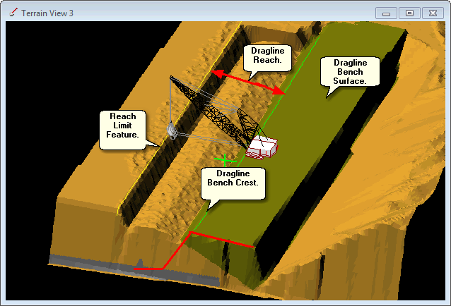
Schematic Diagram Showing Dragline Bench and relevant Features.
Minimum Bench Width field. This field allows input of the Minimum Bench Width parameter as described in the previous section.
Maximum Bench With field. This field allows input of the Maximum Bench Width parameter as described in the previous section.
Bench Face Angle field. This field allows input of the Bench Face Angle parameter as described in the previous section.
Copy Bench Edge Features checkbox. Selecting this checkbox results in the crest and edge feature lines for the bench being copied as Surface Features to the terrain surface. As these Features are generally required for subsequent design, this box should be checked at all times.
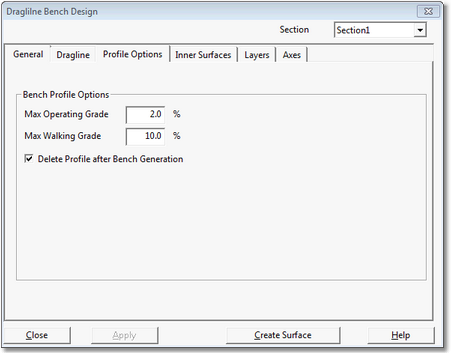
With the above parameters input and the Features selected, the Profile Options can be input. This is done on the Profile Options page of the Dragline Bench Design dialog:
Dragline Bench Design Dialog, Profile Options Page.
The bench Profile Options include two parameters: Maximum Operating Grade and Maximum Walking Grade. These are the standard dragline grade parameters. When the profile is being drawn in section profile elements are colour-coded to indicate conformity with these grades. The system does not automatically constrain the Bench surface to conform to these grades and the user must edit the profile to ensure conformity.
Creating the Dragline Bench Profile.
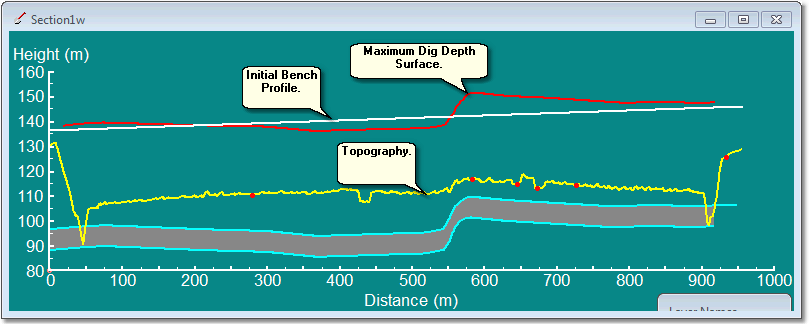
Once the settings on the Profile Options page are complete the user is ready to draw the Bench Profile. To do this the Draw Bench button (Dragline page) is pressed. Pressing this button will open a window to the nominated longitudinal section (selected in the Section pulldown list). When this window is first produced it contains the Initial Bench Profile. This Initial Bench Profile is a straight-line profile joining the two end points in the Section Window:
Longitudinal Section Through Dragline Bench, Initial State.
Designing the Bench Profile involves selecting the Initial Bench Profile line and editing this as required to produce the desired profile. The Longitudinal Section includes the Maximum Dig Depth Surface. This is a surface represented by a red line which indicates the height of the bench at which the dragline is at maximum dig depth. The design Bench Profile cannot be higher than this line without exceeding the draglines' limits.
Editing the Initial Bench Profile in the Section Window involves the following operations:
Point to line, left click and release. Pointing to the Initial Bench Profile line and left clicking and release will select the line. The line will appear highlighted and vertex points will appear with handles.
Point to vertex, left click and drag. Pointing to a vertex handle and holding the left button down while dragging will move the vertex to a new location. The Bench Profile Line must be in the selected state for this operation.
Point to vacant part of line and right click. This action will bring up the following pop-up menu:

Add Point Pop-Up Menu.
Selecting the Add Point option will insert a vertex in the Bench Profile at the current location. Selecting the option Deselect Feature will deselect the currently selected Profile. Once the new vertex is inserted it can be moved to a new location with the above-mentioned Point to vertex left click and drag function. The Bench Profile Line must be In the selected state for this operation.
Point to a vertex and right click. This action will bring up the following pop-up menu:

Delete Point Pop – up Menu.
Selecting the Delete Point option will delete the current vertex. The Bench Profile Line must be in the selected state for this operation.
Using the above functions the Initial Bench Surface is modified to form the design surface via the following steps:
1.Select each of the initial end points in turn and move these so they merge with the topography at the points of entry and egress (ends of the Bench).
2.At any point where a change of grade in the Bench Profile is required add an additional point. Use left click and drag to move these points to the desired location.
3.When complete, click the OK button in the Section Window.
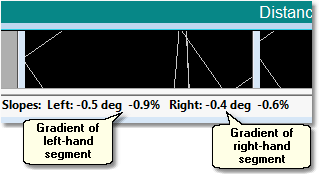
When conducting step 2 as the selected Vertex is moved the gradient of the two adjacent slopes of the Bench Surface is displayed in the 3d-DigPlus status bar at the bottom left of the main 3d-DigPlus window:
Segment Slope Reporting, Main Window Status Bar.
As each point is moved the adjacent slopes are updated dynamically in the Status Bar as shown above. Points are moved to the desired location and the adequacy of adjacent slopes is checked. The completed design should result in a profile which merges smoothly with the topography at the point of entry and egress, and at other locations has slopes that are primarily at or less than the operating gradient. If it is planned to step the dragline up or down at some point in the process a short slope at maximum walking grade is permissible. The slopes of any segment of the Profile can be checked by pointing to a vertex with left click and hold. While ever the left mouse button is held down the slopes will appear as described above in the Status Bar.
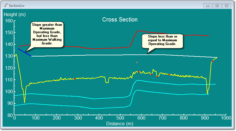
When the editing of the Profile is complete point to a vacant section of the window (away from the profile line) and left click and release. This will deselect the Profile Surface at which point the segments of the Surface will appear colour-coded. The Colour Code is as follows:
White. Slopes are at or less than the Maximum Operating Grade.
Blue. Slopes are greater than the Maximum Operating Grade but less than or equal to the Maximum Walking Grade.
Red. Slopes exceed the Maximum Walking Grade.
Longitudinal Section Along Completed Dragline Bench.
Generally the slope of the Bench should be less than or equal to the Maximum Operating Grade, so over the majority of its length it should appear with the white colour code. Blue colour-coded segments should only appear where a planned step up/step down is located. Red coloured segments are generally not permissible, but there are some exceptions. If a step up/step down is planned, and there is room to manoeuvre the dragline across the pit, the slope as it appears in longitudinal section may be in excess of the Maximum Walking Grade.
When the profile editing is complete the OK button, which appears in the Section Window, is clicked and the focus returns to the Dragline Bench Design dialog. At this stage the Bench setup is complete. A check should be conducted to ensure that the correct name for the Bench is keyed into the Inner Surface Name field at the top of the dialog. Once this is done the Create Surface button can be clicked and 3d-DigPlus will perform the following actions:
1.The Primary Bench Surface will be created. This surface will be given the name which was keyed into the Inner Surface Name field.
2.The Auxiliary Bench Surface will be created. This Surface will be given the name which was keyed into the Inner Surface Name Field and it will be appended with the word "roof".
3.Two Surface Features will be placed on the Terrain Surface, one for the Crest of the Bench and one for the rear edge of the Bench.
Note that action 3 above requires that the Copy Bench Edge Features checkbox in the Bench Parameters group is checked. This Checkbox is checked by default and it is recommended that it be left in this state. If the Bench Edge Features are not required at some stage they can easily be deleted but they cannot be regained without creating a new Bench Surface.
Redesigning or Refining a Bench Profile.
It may be necessary, having completed an initial bench profile, to conduct some modification or redesign of the profile. In such cases the above procedures are repeated. When the Section Window is produced the previous bench profile will appear. There are two options for creating the modified profile:
1.Edit the existing profile using the methods described above.
2.Click the Default button (in the Section Window). This replaces the existing profile with the initial profile.
The following video clip illustrates the process of creating a Dragline Bench:
Using the Bench Surface in a Simulation involves setting up an Area Dump to simulate construction of the Bench. Bench construction consists of dumping material at boom point, and then forming a bench by a combination of dozing and raking of the dumped material. The procedure presented here simulates the bench building as a single step where the excavated material is dumped to the level of the bench.
The Dump Template required for this purpose has the following characteristics:
Dump Type is Area Dump.
Dump Mode is Advancing Dump with Dump Direction set in the cross – bench direction from highwall to low wall.
Dump Constraints are set to Dump to Surface and the Dragline Bench surface is selected as the Constraining Surface.
When the Dump Area is drawn it is placed between the crest of the bench on the highwall side and the rear edge of the bench. The Dragline Bench utility automatically creates two feature lines defining these edges.

Key Information
The above description assumes the bench will be built to the exact design bench width, hence the Primary Bench Surface is used as a constraining surface. Frequently the excavation, whose material reports to the bench, will contain volume in excess of that required to build a minimum width bench. In some cases the excavation will terminate when the bench is complete and the dragline will move to the next block. However in other cases the bench maybe constructed to a greater width using the excess material. As the Primary Bench Surface only extends as far as the minimum bench width it cannot be used to extend the bench. In such cases the Auxiliary Bench Surface (bench roof) should be used. As this bench surface is not constrained in width to the bench design the user must manually place the dump area on or close to the bench crest feature line when using this constraining surface.
The following figures show the relevant Dump Settings:
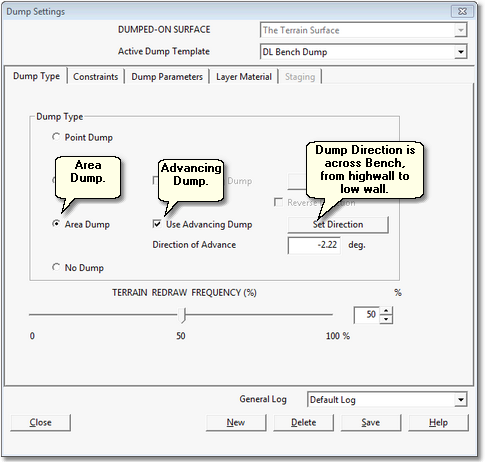
Dump Settings dialog,Dump Type page, set up for Bench Dump.
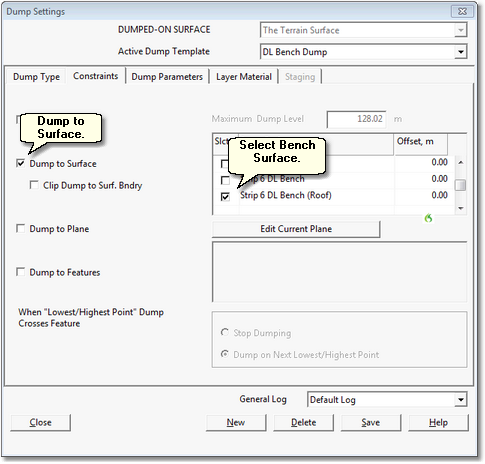
Dump Settings dialog, Constraints page, set up for Bench Dump.
The steps involved in simulating the Bench Area Dump are:
1.Set up the Excavation Polygons for the new Block.
2.Draw the Dump Area for the new Block, this Area extends between the Bench Crest and Bench Edge Features, and extends along the bench for a distance appropriate for the Block being modelled.
3.Run the Simulation.
On completion of step 3 it is likely that the Simulation will have terminated when the dump is full, and at this point the excavation will not be complete. If the function of the current Pass is only to build the Bench, it will be appropriate to leave the incomplete excavation and move to the following Block. If the function of the Pass is to build the bench and excavate to coal, the balance of the excavation will have to be dumped elsewhere. This is handled by a second Dump Template set up for this purpose, and typically this is a line dump which simulates dumping under boom point. Once the Dump Area Polygon for the bench and the Line Dump for the boom point dump exist it is possible to switch between them by right clicking on the dump element (Area or Line) and from the pop-up menu select the option Set Active. This makes the selected element the Active Dump and avoids the need to open the Simulation Settings dialog.
Once the first Dump Area is drawn for the Bench, it is typically possible with each new Block to simply drag the existing dump area to the location for the next Block. This avoids redrawing the Area for each new Block.
The following video clip illustrates a Dragline Simulation dumping to an Area Dump set up to generate the Dragline Bench: