|
<< Click to Display Table of Contents >> Creating Dragline Dumps |
  
|
|
<< Click to Display Table of Contents >> Creating Dragline Dumps |
  
|
The Dragline Moves as described above define precisely how the Excavation for each Move will be executed. The dumps must also be assigned to these moves. These Dumps are created using the Dump Settings dialog and assigned in the Dragline Simulation Settings dialog.
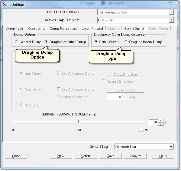
The Dragline Dump is established on the Dump Type page of the Dump Settings dialog:

Dump Settings Dialog - Dump Type Page.
To create a Dump for Automated Dragline Simulation, in the Dump Option group select Dragline or Other Dump. This will enable the Dragline or Other Dump geometry group, in this Group select either Bench Dump or Dragline Boom Dump. Bench Dump will create a bench conforming to a design and Dragline Boom Dump will dump under boom point.
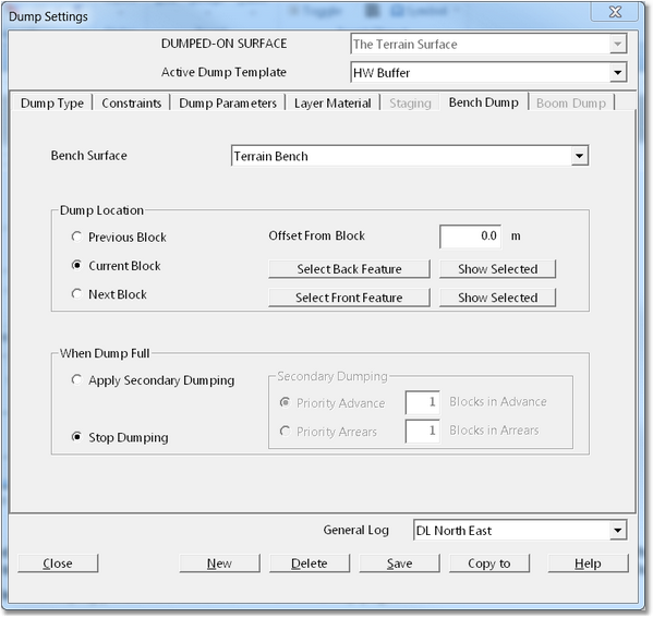
When using Bench Dump the Bench Dumping parameters are set on the Bench Dump page:

Dump Settings Dialog – Bench Dump Page.
The Bench Dump page has the following elements:
Bench Surface pulldown list. The Bench Dump will dump to a predefined Bench Surface. This Surface may be created using 3d-Dig is Dragline Bench function or it can be imported. The appropriate Bench Surface is selected in the Bench Surface pulldown list.
Dump Location Group. The Dump Location Group controls where the boundary of the Bench Dump is located. This includes the cross pit boundaries and the longitudinal boundaries.The the cross pit extents of the bench are controlled by two Surface Features called the Front Feature and the Back Feature. If the Bench Surface has been created using 3d-Digs Bench Surface function these features are automatically created. If the Bench Surface is created a different manner these features will either need to be drawn on the topography or imported. The Back Feature and Front Feature are selected using the Select Back Feature and Select Front Feature buttons.
The Dump Location relative to the block is controlled using the Dump Location radio buttons. The options are:
•Previous Block. The bench will be located in the block before the one currently being excavated.
•Current Block. The bench is created adjacent to the excavation in the same Block.
•Next Block. The Bench is created in the next Block advanced from the block being excavated.
The Bench location can be further refined using the Offset from Block parameter. The desired Offset is keyed into the Offset from Block field and the bench segment which is produced will be offset from the nominated block (Previous, Current or Next) by the nominated Block Offset.
Dump Full Options Group. As a particular Move is excavated its material reports to the nominated Dump. There is no guarantee that this Dump will have sufficient capacity to accommodate all the material excavated by the Move. A successful Automated Simulation requires a strategy to cope with various dumps becoming full prior to complete excavation of the associated Move. There are two distinct strategies available for this purpose:
Dump Hierarchy. When Dumps are assigned to Moves (described in the following topic) there are typically several dumps assigned to a move in order of priority. This is referred to as the Dump Hierarchy. If the first dump in the Hierarchy becomes full material then reports to the next dump and so on. A well designed Dump Hierarchy should be able to cope with the spoil produced from a particular Move the majority of the time.
Secondary Dumping. In some areas of the Strip there will be insufficient spoil room (for a particular block) to accommodate all the waste material adjacent. A coal access ramp is an extreme example of this situation. In such instances the operators may perform a complex sequence of spoil transfer over many blocks to work around the problem. Such highly complex operation is beyond the scope of this automation. However the system of Secondary Dumping has been implemented to allow the system to cope with this situation. Secondary Dumping involves a variant on the Dump Hierarchy where some material for a particular Move is allowed to be dumped in the preceding or following blocks. Secondary Dumping is unable to by selecting the Apply Secondary Dumping radio button. The detail of the Secondary Dumping is controlled by the Priority Advance and Priority Arrears radio buttons together with the number of blocks field. These Radio buttons determine whether the secondary dumping takes place in advance of the draglines current block or in arrears and the Block Number field controls how many blocks may be utilised. If for example the Priority Advance option is selected and 2 blocks are allowed when the current Block becomes full material dump in the next block in advance and if this becomes full the next block in turn will be used.
Key Information – Dump Hierarchies and Secondary Dumping.
 When Secondary Dumping occurs it implies that the full detail of the simulation is temporarily suspended. Material dumped in this manner can be marked so it is clear when this type of processes occurring. In addition a productivity penalty can be applied. Using carefully designed Moves and Dump Hierarchies it is possible, in areas of tight spoiling, to have material rehandled along the pit in a realistic manner and disposed of the spoil when room becomes available. However this is generally limited to areas where the distance between spoil deficit and spoil room availability is no more than a few blocks. It can work with localised spoil room deficits but would not typically work with a large ramp.
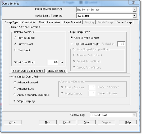
If the Dragline Boom Dump option is selected the Dump is set up on the Boom Dump page:

Dump Settings Dialog – Boom Dump Page.
The Boom Dump Type creates a line dump located on the draglines dump radius. The location of this dump depends on the following:
•The Draglines location. As the Dragline moves so does its dump radius and hence the Boom Dump line. Note that if Position Indexing is used each time the Dragline is re positioned in the process of excavating a Move the dump line is also adjusted.
•Dump Location Parameters. The various parameters on the Boom Dump page are used to determine that segment of the draglines dump radius which represents the valid Dump for the current Dragline Location.
The Boom Dump Page contains the following elements:
Dump Size & Location group. The elements in this group are used to create the basic valid dump line. By default this will be a line along the draglines dump radius but clipped by the block lines for the current block. Using the appropriate radio buttons this can be modified to the Previous block or the Next Block. Further refinement can be done using the Offset from Block parameter which will shift the dump line relative to the nominated block. Note that dumping can also occur across several blocks using settings described below. Dumping is also clipped by a Surface Feature referred to as the Dump Clip Feature. This Feature is designed to delineate valid from nonvalid dump zones. When doing dumping to final spoil this will typically be the low wall toe of the current strip or a spoil berm line. The Dump Clip Feature is nominated by using the Select Dump Feature button.
Clip Dump Circle group. This group allows the full valid dump line to be reduced in size. When the option Clip Full Valid Length is selected the percentage of the full valid length is entered into the percent Maximum Length field. The Position Clipped Dump in Block radio buttons are then used to determine the location of this clipped portion of the dump line.
When Initial Dump Full group. The settings described above allow the basic dump line to be generated. However if the dump constructed with this line becomes full the options in the When Initial Dump Full group can be used to shift the dump line and continued dumping. The Advance Forward and Advance Back options allow the dumping to advance to either the next or the preceding blocks. Generally in order to maintain low swing angles and make full use of spoil room to Dump Size and Location radio buttons will be set to Previous Block and the When Initial Dump Full radio button set to Advance Forward. The option also exists for Secondary Dumping and this is similar to that described for the Bench Dump above.