|
<< Click to Display Table of Contents >> Manipulating Vector Objects |
  
|
|
<< Click to Display Table of Contents >> Manipulating Vector Objects |
|
3d-DigPlus uses a variety of vector objects in the process of designing excavations, dumps and surfaces. The general procedures to manipulating and editing these objects are described in this section. Note that particular object types frequently have additional editing options, the options described here are those general options which apply to all vector objects. Surface features are an example of a vector object and they are used in the following documentation.
The following is a list of vector it functions that apply to most vector objects.
Select/de-select object.
To select a vector object point to the object then left click and release. The selected object will appear highlighted with handles at vertices:
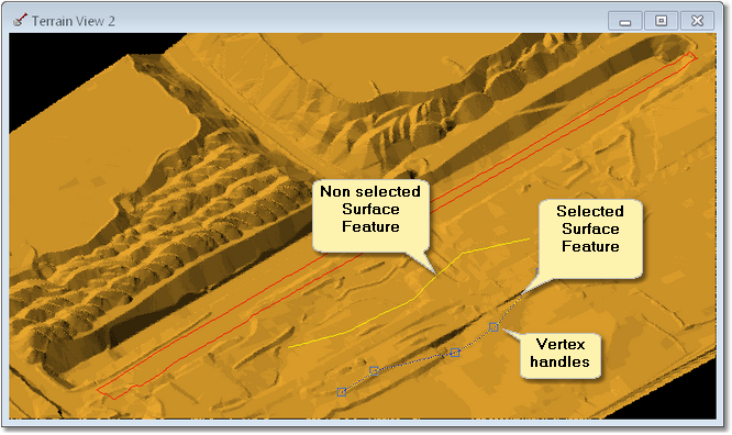
To deselect are selected object, point to an area of topography where no objects exist then left click and release.
Move vector object Vertex.
To move a vertex firstly select the object, then point to the handle of the vertex and left click and drag.
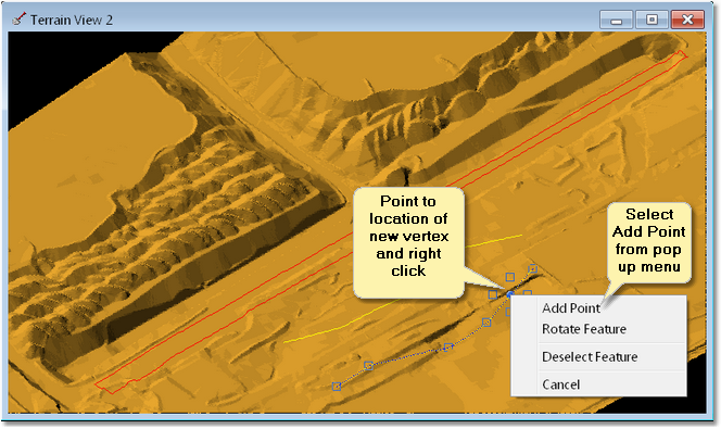
Add a vertex to vector object.
To add a vertex firstly select the object, then apply the following procedure:
•Point to the object approximately halfway between the adjacent vertices.
•Right click to initiate the pop-up menu.
•On the pop-up menu select Add Point.
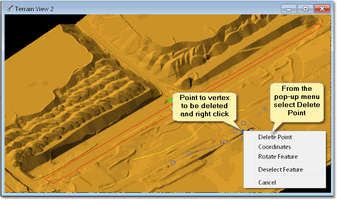
Delete a vertex from a vector object.
To delete a vertex firstly select the object, then apply the following procedure:
•Point to the vertex and right click to initiate the pop-up menu.
•On the pop-up menu select Delete Point.
Move a vector object.
The vector object must initially be de-selected (ie this process cannot be applied to an object which is currently selected).
To move the vector object point to the object, left click and hold, drag the object to the new location and release left mouse button.
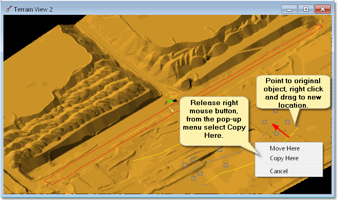
Copy a vector object.
The vector object must initially be de-selected (ie this process cannot be applied to an object which is currently selected).
To copy a vector object point to the object, right click and hold, drag to the location of the new object. On release of the right mouse button a pop-up menu will appear, select Copy Here from the pop-up menu:
Delete a vector object.
To delete a vector object it must initially be in the deselected mode. point to the object, right click and from the pop-up menu select Delete.
The following video clip illustrates the above procedures:
With many object types being selectable, the work area can become crowded with selectable objects. This can make selection of the desired object difficult. 3d-DigPlus has a procedure to allow for the sequential selection of objects.
The first time a selection is attempted the object nearest to the cursor is selected. Thereafter, each time the sequential select command is invoked, the currently selected object is dropped and the next nearest object is selected.
The procedure for sequential selection is:
•Point to the desired object, click the left mouse button and hold.
•The “first” object will be selected, if this is not the desired object, press and hold the Ctrl key (continue holding left button).
•With the Ctrl key pressed, repeated release and left clicking will select sequential objects.
Some selectable objects in 3d-DigPlus may be Copied or Cut to the clipboard, or deleted after selection using standard editing functionality. This applies chiefly to Data Features and Surface Features.
A number of such “cut-able” objects may be selected simultaneously in 3d-DigPlus using two methods:
1.Hold the Shift key while selecting objects in the usual way by pointing with the mouse cursor and clicking the left mouse button. Each object selected in this way is added to the group of objects already selected.
2.Use the rectangle or irregular tool on the toolbar to select a number of objects. these tools allow the user to draw either a rectangle or an irregular polygon. All candidate vector objects falling within the rectangle polygon will be selected.
The figure below shows the rectangular and irregular select toolbar buttons:

Select Tools Toolbar Buttons.
Such simultaneously selected objects are then treated as a group and various operations may be applied to them simultaneously.
Many operations require vector objects to be precisely located. There are a number of means available to achieve this, snapping to other vector objects for creating the current object is one means of achieving precise location. An example of this is the creation of excavation polygons. Frequently these polygons will be snapped to a surface feature which represents the limit of excavation.
To snap to an existing vector object the following procedure is used:
1.Initiate the command to create the current vector object (e.g. draw Inner Polygon).
2.Move the Terrain Cursor on top of the vector object to which the new object will be snapped.
3.Hold down the CTRL button, left click and release (mouse button) then release the CTRL button.
4.The cursor will now be snapped to the vector object and will respond to SIDEWAYS mouse movement.
5.By moving the mouse sideways move the cursor along the snapped object to the desired end point and left click.
6.The snap portion of the new vector object will now be complete, continue placing the remainder of the object freehand.
If after step three the cursor does not snap to the vector object, move the cursor again on top of the object and repeat the process. If it is necessary to snap to several vector objects repeat the snap procedure on as many objects as required.
The following video clip illustrates snapping to a Surface Feature when placing an excavation polygon: