|
<< Click to Display Table of Contents >> Terrain Editor Settings |
  
|
|
<< Click to Display Table of Contents >> Terrain Editor Settings |
  
|
The Terrain Editor Settings contain a series of commands and settings that modify and control the behaviour of surface models.
Selecting the main menu item Terrain/Editor settings produces the Terrain Editor Settings dialog. This dialog contains four pages.
General page.

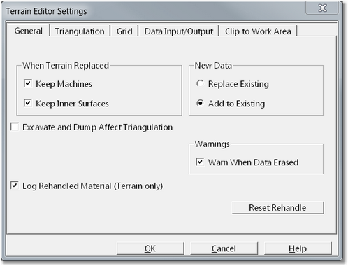
Terrain Editor Settings dialog, General page.
The General page contains the following items:
When Terrain Replaced group. Could this group consists of two checkboxes which affects the way 3d-DigPlus behaves when the Terrain Surface is replaced by new imported data. The two checkboxes are titled Keep Machines and Keep In a Surfaces. If these checkboxes are not selected, and new terrain data is imported to replace the Terrain Surface, all pre-existing inner surfaces and machines are deleted in the process. As most design elements in 3d-DigPlus are based on Inner Surfaces these will also be deleted. If these two checkboxes are selected Inner Surfaces, Machines and most items in the 3d-DigPlus file will be kept when you terrain data are loaded. In situations where loading new terrain data is intended to update the existing Terrain Surfaces, the options Keep Machines and Keep Inner Surfaces should be selected.
New Data group. This group consists of two checkboxes titled Replace Existing and Add to Existing. These checkboxes control the behaviour of the system when new data are imported into an existing Inner Surface, or into the Terrain Surface when data already exists for the surface. If the option Replace Existing is selected, the system assumes the new data supersede the existing data and consequently the existing data is replaced with the new. If the option Add to Existing is selected the system assumes that data from several sources must be accumulated to model a surface and each time a new data file is loaded it's data is added to the existing data for the surface.
Excavate and Dump Affect Triangulation. Excavation and Dump modelling in 3d-DigPlus is done using the Grid model for the Terrain Surface. The original triangulation model is not affected by excavation and dumping. If the Excavate and Dump Affect Triangulation option is selected, the excavation and dump modelling performed on the grid is subsequently transferred to the triangulation model. This functionality is currently under development and it is recommended that this option be deselected at all times.
Warn When Data Erased checkbox. This option is on by default and every time an action is initiated by the user which deletes data in a surface a warning is issued. If you do not wish to have this morning it can be disabled by this checkbox.
Log Rehandled Material checkbox. This checkboxes on by default,and enables the creation of the Prime Surface and rehandle logging. See Prime Surface and Rehandle topic.
Reset Rehandle button. This button will reset the Prime Surface to the current state of the Terrain Surface. Initiating this command will effectively delete all previous rehandle modelling in the 3d-DigPlus file. A warning is issued prior to resetting the Prime Surface.
Triangulation Page
The Triangulation Page provides access to triangulation settings described in the topic Data Input.

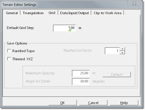
Terrain Editor Settings - Grid page.
The Grid page contains the following items:
Default Grid Step. This field allows the default grid step to be modified. The default grid step is used when all surfaces up automatically gridded by a 3d-DigPlus process. In a typical file set up the Terrain Surface is imported and manually gridded by the user using a grid step is set by the user. All other Inner Surfaces are usually triangulated and gridded automatically as required. The normal default grid step is 3.0 m. This is generally adequate for use with Inner Surfaces. However if you wish to modify this default is done via the Default Grid Step parameter.
Save Options group. Data from a surfaces grid model can be exported to a DXF file using the File/Export option. The parameters in the Save Options group control how it data from a grid model are processed during this export function. the options are:
•Rarefied Topo. This is the most basic option and simply rarefies the surfaces grid according to the specified Rarefaction Factor. If a a Rarefaction Factor of 1 is selected the full grid is exported. If a Rarefaction Factor of 2 is selected every second grid point is exported. Using a Rarefaction Factor greater than 1 reduces the size of the DXF file but also significantly reduces the resolution of the data.
•Thinned XYZ. This is a more sophisticated option for grid thinning. It users two parameters: Maximum Spacing and Angle for Detail. Areas of the topography where the gradient is greater than the Angle for Detail will be exported with all original grid point is retained. Areas of the topography where the gradient is less than the Angle for Detail will be thinned in a manner similar to that described above for Rarefied Topo subject to the Maximum Grid Spacing parameter. Best results are generally achieved if an Angle for Detail of just less than the repose angle is selected. in this case the areas of spoil plus highwall and in wall batters will be adequately resolved in the exported data set.
 Tip - Exporting Surfaces.
Although surfaces can be exported by the grid options above, best results are generally achieved by creating a suitable Contour Window for the surface and exporting these contours. These procedures are described in the topicExporting Surfaces.

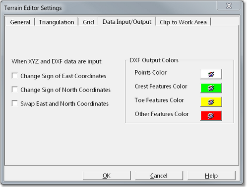
Terrain Editor Settings dialog - Data Input/Output page
The settings on this page control the way 3d-DigPlus interprets the structure of files during import and export operations. This page contains two groups:
When XYZ and DXF data are input group. By default 3d-DigPlus expects DXF files to contain one data point per line with the order: easting, northing, RL. The When XYZ and DXF data are input group allows some modification of this format. This group consists of three checkboxes that control the order of items as they are interpreted when a file is imported or as they are placed when a file is exported.
DXF Output Colours group. This group provides colour selectors to control the colour of particular items when they are exported to a DXF file.
 Warning - Clipping Data.
The process of clipping to Work Area is irreversible. Once complete all clipped data are permanently clipped. It is therefore critically important to save a copy of the 3d-DigPlus file prior to performing any data clipping.

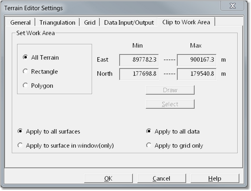
Terrain Editor Settings dialog - Clip to Work Area page.
The settings and functions on the To Work area page allows surfaces to be cropped to user nominated area. At the bottom left of this dialog are two radio buttons which control which Surfaces the cropping applies to:
•Apply to all surfaces. When this option is selected all surfaces in the file (Terrain and all Inner Surfaces) are cropped.
•Apply to surface in window only. When this option is selected only the Surface in the active window is cropped.
There are three modes of cropping the work area which are selected via radio buttons:
All Terrain. This option uses the boundary of the Terrain Surface. When used in conjunction with the Apply to all surfaces option all Inner Surfaces are cropped to the boundary of the Terrain Surface. This command is useful if the imported geological models extend well beyond the topography. It provides automatic cropping of all Inner Surfaces to the boundary of Terrain Surface.
Rectangle. This option allows the Terrain to be cropped with a rectangular boundary. When this option is selected, and the user clicks the Draw button, the Editor Settings dialog is temporarily dismissed and focus moves to the Terrain Window. A rectangular boundary is selected by moving the cursor to the top left corner of the required boundary. The left mouse button is pressed and held down, as the mouse is subsequently moved (with the button-down) a rectangle is dragged out. When the rectangle covers the design area the left button is released. Focus returns to the Terrain Editor dialog. When the OK button is clicked the cropping action is performed.
Polygon. This option behaves in a similar manner to the Rectangle described above except that the user can draw at irregular polygon rather than a rectangle. If a suitable close polygon exists in the window the Select button can be used allowing the user to select the pre-existing polygon. Once the polygon is drawn or selected focus returns to the Terrain Editor dialog. Clicking the OK button will implement the cropping action.
To crop surfaces in the file the following procedure is used:
1.As the Clip to Work area command will put the active window in plan view mode is best to manually place the window in plan view mode prior to initiating the command. This will ensure that all of the desired area is still visible in the window when it is in plan view mode.
2.From the main menu select Terrain/Editor Settings to open the Terrain Editor Settings dialog.
3.Click on the Clip to Work Area tab. Owhenn the Set to Work Area page select the desired work area type (All Terrain, Rectangle or Polygon).
4.Select the appropriate surface group method (all surfaces or surface in window only).
5.Click the Draw button and in the Terrain Window mark out the area for cropping.
6.Click the OK button to apply to cropping action.