|
<< Click to Display Table of Contents >> Surface Functions |
  
|
|
<< Click to Display Table of Contents >> Surface Functions |
|
The terrain surface functions are accessed by the main menu item Terrain/Surfaces which opens up the submenu:
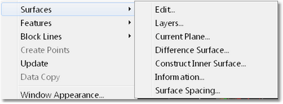
Surfaces/Edit.
The Surfaces Edit command opens up the Edit Surface dialog:
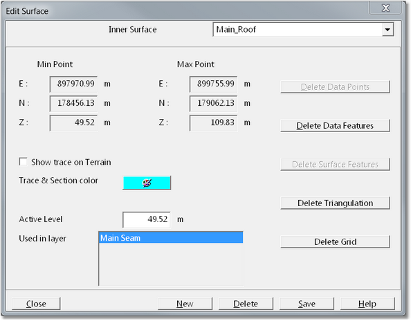
The Surfaces Edit dialog contains the following items:
Surface Pulldown List (top right of dialog box). This pulldown list includes all surfaces in the 3d-DigPlus file. The Surface to be edited or modified is firstly selected from this list, all subsequent information and functions accessed from the dialog box will apply to the selected surface.
Min Point and Max Point groups. The Min point and Max Point groups consist of easting, northing and RL coordinates. These are the coordinates at the extreme ends of a rectangle pounding the data set. The location and span of the data set is represented by these points.
Surface Element Delete Buttons. Down the right-hand side of the dialog are five buttons which allow the deletion of various surface elements. When a surface is imported into 3d-DigPlus the data typically consists of Data Features (break lines) and Points (spot heights). These data are then subject to triangulation which produces a triangulated surface model and finally gritting which produces the surface grid. Once a grid model is produced the source data and triangulation can typically be deleted. If the original source data set is large deleting Data Features, Points and Triangulation can significantly reduce the 3d-DigPlus file size. The Surface Element Delete Buttons are:
Delete Data Features. This button deletes all Data Features in the data set for the selected surface.
Delete Points. This button deletes all Data Points in the data set for the select surface.
Delete Surface Features. This button deletes all Surface Features imported onto the selected surface. Note that Surface Features are not part of the data model, they are design elements that appear on the surface in rendered views. Where it is necessary to delete Surface Features this is typically done in a Terrain Window by selecting individual Surface Features or groups of Surface Features then deleting them. The Delete Surface Features button is typically only used in situations where a very large number of Surface Features have been imported onto a surface and the user needs to delete all these features.
Delete Triangulation. This button deletes the triangulated model for the selected surface.
Delete Grid. This button deletes the Grid model for the selected surface. Deletion of the Grid model is rarely required or appropriate.
Show Trace on Terrain checkbox. When this checkbox is selected the line of intersection between the selected surface and the Terrain Surface will be displayed in all rendered Windows. The following figure shows the surface trace for a coal seam which is exposed in the highwall:
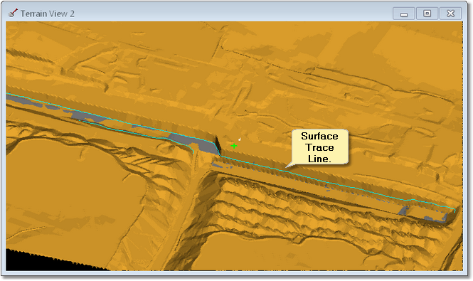
It is possible to snap to Surface Trace Lines when creating other vector objects.
Trace and Section Colour selector. This colour selector determines the colour used for Surface Trace Lines and also the colour used for the selected Surface in Cross Section Windows.
Used in Layer List. This list shows every Layer in which the selected Surfaces used.
This command opens the Layers dialog allowing the creation of Layers. This is described in the topic Setting up Layers.
The Current Plane functionality allows the creation of a planar inner surface.
The plane is created by specifying the various parameters that the system uses to generate the plane. The definitions of these parameters are shown in the following figure:

Current Plane.
The Current Plane is defined by a direction, gradient, cross-fall and height reference. Note that the crossfall is typically 0.0 (no cross fall), the gradient can also be set to 0.0 creating a horizontal surface.
When the Current Plane command is selected the Current Plane dialog is produced. The first page of the Current Plane dialog is the Slopes page:

Current Plane dialog, Slopes page.
The Slopes page contains the following elements:
Gradient Direction field. This field contains the direction, relative to North, of the gradient. The gradient direction can be keyed in if it is known, alternatively it can be set graphically using the Set button.
Set (set gradient direction) button. When clicked this button temporarily dismisses the Current Plane dialog. Focus moves to the Terrain Window where the Terrain Cursor responds to mouse movement. the Terrain Cursor is moved to a start point and a left click is performed. As the Terrain Cursor is moved further a direction arrow is dragged out indicating the Gradient Direction. When the arrow is pointing in the appropriate direction a second left click registers this direction which is placed in the Gradient Direction field.
Cross Fall. If a cross fall is required to cross fall angle is placed in the cross fall field.
When the Gradient and Gradient direction are defined the user clicks the Coordinates tab to open the Coordinates page:

Current Plane Dialog, Coordinates page.
At the top of the coordinates page is the Surface Bounds group. The fields in the Surface Bounds group allow the user to key in the coordinates for a minimum and maximum point which will define a bounding rectangle for the Current Plane surface. This determines the planar extents of the surface. There is also a Set from Terrain button. If the Set from Terrain button is clicked the bounds of the Current Plane surface are set to the bounds of the Terrain Surface. If the user takes no action in the Surface Bounce Group, the Current Plane is automatically set to the bounds of the Terrain Surface. As this is typically what is required, there is usually no need to modify the Surface Bounds.
At the bottom of the Coordinates page is the Reference Point group. Having previously defined the Gradient and Gradient direction, the elevation of the Current Plane must be defined. This is done via a reference point. The Reference Point is a point on the plane where the elevation is known.This is typically set using the Set Reference Point button. When the Set Reference Point button is clicked a Current Plane dialog is temporarily dismissed and focus returns to the Terrain Window. The Terrain Cursor is active in the Terrain Window and its move to a location on the terrain will the elevation of the Current Plane is known. This is usually a point where the Current Plane it intersects the Terrain Surface. When the Terrain Cursor is at this reference point left click is performed. This Set Reference Point dialog is produced:

Set Reference Point dialog.
The Set Reference Point dialog has a field in which the reference point height is entered. By default this is the elevation of the terrain at the nominated reference point. As the Reference Point is typically the point where the Current Plane intersects the Terrain Surface, this default value is often the required value of the Reference Point. When the Reference Point number has been entered the OK button is clicked and focus returns to the Current Plane dialog.
At this stage the Current Plane is fully defined as ready to be saved. Clicking on the Save to Surface tab opens up the Save to Surface page:

Current Plane Dialog Save page.
There are three options for saving the plane.
Using the Choose In a Surface pulldown list an existing In a Surface can be selected. When the Saved to Chosen In a Surface button is clicked the surface defined by the Current Plane set up will be saved in to the nominated In a Surface.
Clicking the Saved to New Inner Surface button produces a dialog which allows the user to name a new In a Surface. The surface defined by the Current Plane set up will be saved to this surface.
At the bottom of the dialog is a button named Save to *Current Plane*. When this button is clicked 3d-DigPlus creates a special surface named *Current Plane*. The surface defined by the Current Plane set up will be saved to this surface. If the Current Plane command has been run previously and the *Current Plane* surface exists, clicking the Save to *Current Plane* button will overwrite the existing *Current Plane* surface with the new Current Plane surface.
The following video clip illustrates the process of creating a Current Plane surface:
The difference surface functionality allows a difference surface (isopach) to be created from two starting surfaces. The procedure works as follows:
The user nominates the two surfaces. These are referred to as the first and second surfaces. 3d-DigPlus determines the boundary of each surface and the boundary of their region of overlap. This region of overlap becomes the difference boundary.
A grid is generated, aligned with the east and north directions. This grid covers the Difference Surface region. At each grid point, the height of the first and second surfaces is determined. The second surface height is subtracted from the first surface height. This difference becomes the value of the difference surface at that point.
The command is accessed using Terrain/Surfaces/Difference Surface. This produces the Difference Surface dialog:

Difference Surface Dialog.
The name of the new difference surface is entered into the Difference Surface Name field. The First and Second surfaces are selected using the surface select pull-down list. The desired grid step for the difference surface is entered into the Grid Step field.
The difference surface is initially formed as a grid model, without the use of a triangulation. The user can nominate to produce a triangulated model and data via the Create triangulation and data checkbox.
When the dialog box set up is complete, click the Create button to build the difference surface. The difference surface will now exist. It can be viewed as other surfaces using the Terrain Appearance dialog box.
Surfaces/Construct Inner Surface.
The construct surface command allows an inner surface to be constructed via a cross section window. The user draws the profile of the inner surface in the cross-section window, the Construct Inner Surface command then creates a three-dimensional line based on this profile and the cross-section location, this is known as the seed feature line. The system creates a new inner surface and the newly created seed feature line is placed in the surface. Two additional copies of the seed feature are created on either side of the original feature. The offset distance between the original seed feature and the copies is controlled by user settable parameter. When the process is complete the system triangulate and grid is the new inner surface.
Before initiating this command a suitable cross-section must exist and it's section window must be active. The cross-section at approximately the centre of the required surface and normal to the axis of the surface. When the command is initiated the Construct Inner Surface dialog is produced:

Construct Inner Surface dialog.
The name for the new surface is entered in the Inner Surface Name field .The Surface Extent group contains settings which control how far the new surface will extend relative to the section line. If the option Full Extent of Terrain is selected the surface will extend, normal to the original section line, to the full extent of the Terrain Surface. If the Specified Horizontal Distance option is selected the surface will extend beyond the original cross-section by distances specified in the to field is Into Section and Out of Section. This is illustrated in the figure below. Note that in this figure two features copied to form the surface are shown on the Terrain Surface, these features only exist in the data for the newly constructed surface:

Location of Features generated by Construct Inner Surface function.
To command can optionally generate a grid model of the surface and this function is controlled by the Grid group. Selecting the checkbox Create Grid for Surface and specifying the Grid Step will result in a grid model being produced.
To design the surface the user clicks the Draw Feature button. The Construct Inner Surface dialog is temporarily dismissed and focus moves to the Cross Section window. The user draws that design surface profile in the Section Window by pointing and left clicking. When the feature is complete a right click terminates this process and returns focus to the Construct Inner Surface dialog. The figure below shows a surface profile for a bench surface drawn in the section window:

Surface Profile in Section Window.
To complete the process to Create Surface button is pressed. This results in the system constructing the new Inner Surface according to the user specifications.
The figure below show the surface constructed as described above in a data window:

Constructed Inner Surface - Data Window.
Surfaces/Information.
The Surfaces Information command produces the Surfaces Information dialog:

Surface Information dialog.
The Surface Information dialog provides information on the physical extents of the surface and the surface model is present.
The Surface Spacing command provides information on the elevation (RL) of all surfaces present at the current location of the Terrain Cursor. It represents a virtual borehole log at the location of the Terrain Cursor. When the command was initiated the Surface Spacing dialog is produced:

Surface Spacing dialog.
At the top of the Surface Spacing dialog is a field called Current Surface. The surface shown in this field is the surface in the active Terrain Window at the time the command was initiated. It is almost always the case that this will be the Terrain Surface, however 3d-DigPlus does allow for this command to be initiated from window is displaying other Inner Surfaces.
The easting northing and RL of the current Terrain Cursor location are listed below the Current Surface field.
The Surface List group contains a list of all Inner Surfaces. For all surfaces present the following data are presented in columns:
•Z. This is the RL of the surface at the location of the Terrain Cursor.
•Depth. This is the depth of cover to the surface from the surface listed in the Current Surface field. In most instances this is the depth of cover from the terrain to the surface.
•Z Diff. This is the difference in elevation between the surface to which the field applies and the surface immediately above. For any given surface the Z Diff is the thickness of the horizon from this surface to the surface immediately above.
At the top of the Surface List group are two pulldown lists titled 1st (surface) and 2nd (surface). These pulldown list can be used to select any Inner Surfaces. These surfaces are then used when the user accesses the Move Cursor command. At the bottom of the Surface Spacing dialog is a button titled Move Cursor. When the Move Cursor button is selected the Surface Spacing dialog is temporarily dismissed and focus moves to the Terrain Window. The Terrain Cursor is active and response to mouse movement. As the Terrain Cursor is moved information is displayed dynamically in the 3d-DigPlus status bar. This information pertains to the two surfaces selected in 1st (surface) and 2nd (surface) . The following information is presented in the status bar:
E. Easting of current Terrain Cursor location.
N. Northing of current Terrain Cursor location.
Z. RL of current Terrain Cursor location.
1st Z. RL of 1st Inner Surface at current Terrain Cursor location.
1st Depth. Depth of cover to 1st Inner Surface at current Terrain Cursor location.
2nd Z. RL of 2nd Inner Surface at current Terrain Cursor location.
2nd Depth. Depth of cover to 2nd Inner Surface at current Terrain Cursor location.
Diff. RL difference between v2nd and 1st Inner Surface at current Terrain Cursor location.
Bearing. Bearing between current Terrain Cursor location and original Terrain Cursor location.
Dip. Vertical angle between current Terrain Cursor location and original Terrain Cursor location.
By nominating the roof and floor surfaces for a particular coal seam as the 1st and 2nd surfaces, the user can move the cursor and dynamically see the depth of cover and coal seam thickness at any point.
The Terrain/Update function allows point cloud data to be imported and used to update the topography. Point cloud data is very dense spot height data acquired by laser face profiling instruments. This function is used in situations where a face profiler is used to acquire an updated survey of portion of a pre-existing topography. This updated data is located entirely within the bounds of the pre-existing topographic model. Picking up a blast profile, or the topography after a first pass dragline operation are examples when of situations where the Terrain/Update function would be used.
When the Terrain/Update command was initiated the Update Terrain dialog is produced:

Update Terrain dialog.
The Update Terrain dialog contains the following elements:
Update Grid checkbox. When this box is checked the surfaces' grid model will be updated by the process.
Update Data and Triangulation checkbox. When this box is checked the surfaces data and triangulation will be updated by the process.
Maximum Point Spacing field. This allows the user to input the Maximum Point Spacing parameter. Point cloud data typically have a very high point density with points closely spaced. Due to occlusion such data sets often have a very convoluted boundary. If the such data sets are subject to Delaunay triangulation, triangles will form a cross the concave areas of occlusion. the Terrain Update function as algorithms which use the close point spacing to exclude occluded zones from the data update. The Maximum Point Spacing parameter is used in this process. This parameter should be set to a number which is higher than the typical point spacing within the point cloud.
Source File. This is the file containing the point cloud data, is accessed by clicking the Browse button.
Update button. When all settings are complete clicking the update button will import the point cloud data and update the topography.
The Terrain/Data Copy command allows data from one surface to be copied into an other surface.
Prior to initiating the Terrain/Data Copy command a data window for the target surface must be active. When the Terrain/Data Copy command is initiated the Terrain Data Copy dialog is produced:

Data Copy dialog.
The Terrain Data Copy dialog contains the following elements:
Region radio buttons. These radio buttons control the extents of the copied data. The options are:
•All Surface. This option results in all the data from the source surface being copied to the target surface.
•Rectangle. This allows the user to draw a rectangle in the data window for the target surface, data from the source surface within the bounds of this rectangle will be copied to the target surface.
•Polygon. This allows the user to draw polygon in the data window from the target surface, data from the source surface within the bounds of this polygon will be copied to the target surface.
Set Region button. When the Set Region button is clicked the Terrain Cursor becomes active in the active Terrain Window. The user draws the rectangle or polygon (depending on above settings) to define the region in which data will be copied. Note That the active Terrain Window must be a data window for the target surface.
Surface Name pulldown list. This pulldown list contains all surfaces in 3d-DigPlus file. The surface selected is the source surface for the data copy.
When the the source surface is selected, and the region defined, the OK button is clicked and data are copied from the source surface to the target surface within the nominated region.