|
<< Click to Display Table of Contents >> Procedures for Surface Reshaping |
  
|
|
<< Click to Display Table of Contents >> Procedures for Surface Reshaping |
  
|
Once the user has an understanding of the procedures for setting up the regions and basic reshaping, proficiency will be acquired with experience applying the system to a variety of reshaping problems. The following description is not a substitute for gaining this experience but is intended to give the user an indication of how to approach typical reshaping tasks.
Polygon (Region) Placement
Reshaping regions are used for two purposes, the limit the distance through which material has to be transported to produce the design surface and to assist in achieving the desired form of the reshaped surface.
When the reshaping takes place the reshaping algorithm has no knowledge of the distance through which material will have to be transported to produce the design surface. It guarantees volume balance within the reshaping region but not distance moved. The control over distance is achieved by carefully placing regions. Volume balance is always guaranteed within any given region.
The best way to approach region placement initially is to think of how the dozer fleet will approach the task of reshaping and place regions consistent with small complete dozing tasks. The following describes a few common scenarios.
Perimeter spoil. Perimeter spoil typically consists of a high, long spoil slope merging onto the surrounding (typically flat) topography. The following figure illustrates typical perimeter spoil:
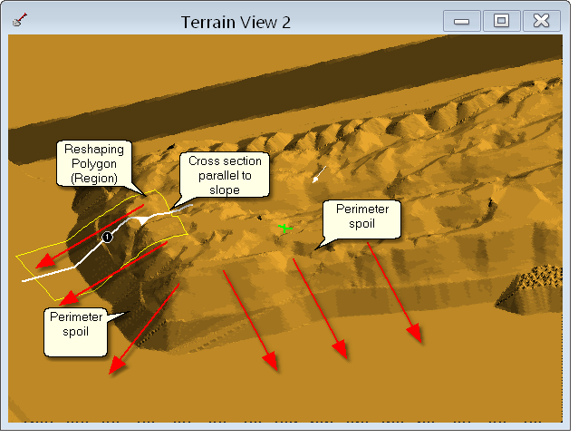
Perimeter Spoil.
It is often the case that the perimeter spoil will contain, area and volume wise, the bulk of the earthworks.The regions should be placed so they extend approximately from the top (crest) to the toe of the final reshaped slope. If the length of a Polygon is not sufficiently long to form the desired slope the reshaping algorithm will not be able to form this slope. Depending on the reshaping parameters used, the surface will settle at the lowest slope possible within the constraints of the Polygon:
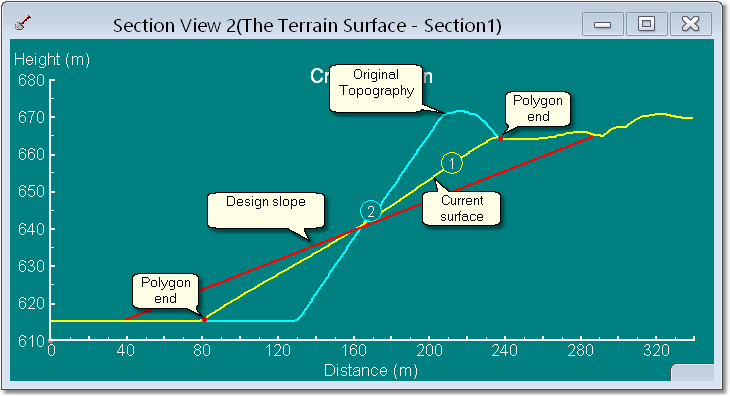
Spoil Reshaping limited by Polygon Geometry.
In the above figure the slope is been reduced to a straight line between the two polygon ends. This is the least slope surface which can be achieved subject to the constraint of the polygon. Any repeated attempts to reshape beyond the state will result in either no change to the reshaped surface or possibly a concave or convex form occurring. In this situation the polygon would need to be edited and its length expanded at each end.
 Tip - Physical Constraints on Spoil Movement
If a physical constraint, such as road, limits the available length of slope, it may not be possible to extend the polygon and achieve the desired slope. In such cases the design slope cannot be achieved without a bulk earthworks operation to transfer spoil from the region at the top of the slope to some available fill point on the topography. In such cases 3d-Digs cut and fill functionality can be used to perform this bulk earthworks prior to or during the reshaping process.
With experience the user will be able to make a close initial estimate of the required Polygon length. If you are unsure it is possible to draw a cross-section to estimate the likely location of the final slope. The cross-section should be drawn parallel to the slope of the parameter spoil (as in the above figure), and extend further in both directions than the extent of the final slope. In the Section Window estimate where the toe will be put the cursor on this location and left click to set an anchor point. Now move the cursor up to the estimated location of the final slope crest. The status bar at the bottom of the 3d-Dig window displays but the distance and slope line which extends between the anchor point and the current cursor location.The following figures illustrate this:
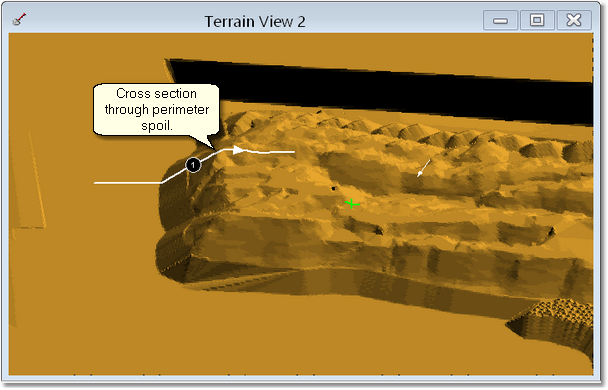
Using Cross Section to Place Region – Section Placement.
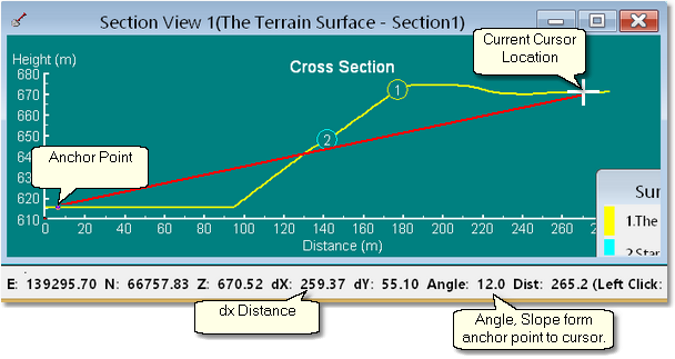
Using Cross Section to Place Region – Section Window.
This process is intended to be a quick means of assessing the location for the reshaping Polygon. Polygons do not need to be precisely placed initially and typically Polygons will require editing during the design process. With experience the user should be able to estimate a suitable Polygon location "Freehand". Once the initial Region is placed, provided the adjacent spoil geometry is similar, subsequent regions can be placed in a similar manner to the first. The following video clip illustrates this process:
 Tip - Use of Cross Sections to Monitor Evolving Reshaped Surface.
In the above example a Cross Section was used to establish the initial Reshaping Polygon. The use of Cross Sections parallel the primary slope is also useful to monitor the slope during the reshaping process. The current slope magnitude can be checked in cross-section. The Reshaping Polygon will be visible in the cross-section and hence you can check with the length of the Polygon is appropriate. Typically only one Cross Section is required this can be dragged from Polygon to Polygon as necessary.
Corner Spoil. Spoil corners typically occur within perimeter spoil. They consist of inside and outside corners. Frequently a single splayed polygon is sufficient will to adequately handle a corner, sometimes several polygons will be required. The following figures illustrate this:
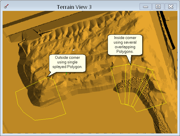
Corner Spoil.
Ramp Spoil. The term ramp spoil is used to describe situation where a deep access ramp penetrates the spoil. A low wall coal access ramp in a dragline pit is a typical example. There are two types of Polygon geometry which are suitable for reshaping ramp spoil:
•A single polygon spanning the full width of the ramp.
•Two overlapping polygons approaching the ramp void from opposite sides.
The following figure illustrates ramp spoil and the two polygon geometries.
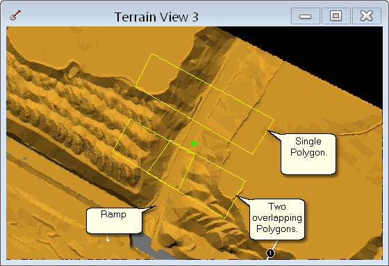
Ramp Spoil.
Where two overlapping Polygons are used each Polygon is intended to reshape one side of the ramp. However the toe end of the Polygons needs to extend beyond the ramp centreline, as illustrated in the figure above. When using this type of geometry one Polygon is selected initially and subject to a number of reshaping iterations, then the opposite Polygon is selected and subject to the same iterations. The first polygon is then selected and subject to additional iterations and so the process continues. It is important that each Polygon is processed in turn rather than trying to complete the reshaping on one side of the ramp and then continue on the other.
The use of a single Polygon reduces the amount of work required to reshape a large ramp. However this method is most suitable with the two sides of the ramp share a similar geometry, in particular the spoil height on each side needs to be about the same. If the situation emerges where the slope on one side of the ramp is at the design slope and the other still requires significant reshaping, then a polygon will be required for the steeper side so it can be reshaped independently.
When reshaping ramps it is generally best to use a Straightness Coefficient of 4 or greater. Using a lower Straightness Coefficient can result in some rounding at the base of the slopes in the area of the ramp floor. This rounding may be desirable, however it is often required that the two adjacent slopes join with little or no rounding. The following topic Adjusting Reshaping Parameters explains this concept further.
Interior dragline spoil. Interior dragline spoil refers to dragline spoil away from the influence of perimeter spoil, ramps and pit void. This typically consists of long linear spoil piles with a frequency of between 50 and 70 m. When planning a reshaping exercise any perimeter, ramp or void spoil should be processed before moving onto the interior spoil. The reshaping of these initial spoils will generally penetrate well into the interior and hence consume any interior spoil which had already been reshaped.
As the interior dragline spoil is typically of modest height and modest slope length slopes will generally be reduced the design slopes with far fewer iterations that are required for the longer perimeter spoil. This can however be problematic as it is easy to produce too much slope reduction. Keep in mind that the Undo button can be used with the reshaping process. Therefore if a slope is reduced excessively use the undo button, several times if necessary, to revert back to a steeper slope and continue.
Dragline spoil typically displays a highly irregular form with vast numbers of individual small spoil peaks existing within the lines of spoil. The 3d-Dig reshaping algorithm can handle this spoil form but consideration needs to be given to the the accuracy and implementation issues discussed at the beginning of this section. Attempting to get every individual slope very close to design slope in all areas can be time-consuming and given the issues with implementaion it Is unlikely that this type of spoil can be reshaped sufficiently precisely to a design to justify this detail. Is recommended therefore that the user target near approximation of the design slopes. This will typically be sufficient to provide A good estimate of volumes and costs and provide the bulldozer operators with sufficient guidance to efficiently produce the rehabilitated surface.
The polygons used for dragline spoil reshaping should be placed given consideration to localised spoil transport. The approach taken to placing these polygons is similar to that described above for ramp reshaping. Reshaping two adjoining rows of dragline spoil with a common trough between them is the same geometry, on a smaller scale, to that described above for ramp rehabilitation. Polygons can be placed which encompass two adjacent spoil piles and a common trough or individual polygons can be placed for each slope as illustrated in the following figure:
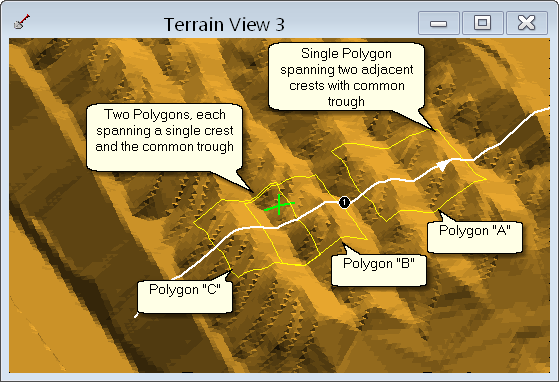
Polygon Placement for Dragline Spoil Reshaping.
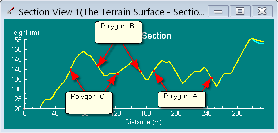
Polygon Placement for Dragline Spoil Reshaping - Section View.
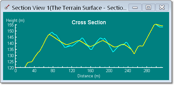
Dragline Spoil Agter 4000 Reshaping Iterations.
For clarity the above figures display one row of reshaping Polygons. In a complete job there will be several adjacent overlapping rows of such polygons. Each row of Polygons should be processed in turn for each run of reshaping iterations. In this manner the slopes for the entire design area are gradually reduced in unison.
The use of individual polygons for each slope is generally the best option as it provides greater control over the final slope. When one slope reaches an acceptable gradient this polygon can be omitted from future reshaping iterations.
For approximate or conceptual design it is sometimes possible to use large polygons spanning many crests and troughs. However care needs to be taken with this approach as can be difficult to control individual slopes and material transport distances. Generally this approach works best if the Straightness Coefficient is set to 4 or higher.
Void Fill. Void fill describes the situation where spoil is pushed down to fill or partially fill a final void. If the void is to be filled completely it is best to start using 3d-Digs cut and fill functionality to model the bulk earthworks in advance of modelling the final smoothing. The following description applies to a partial fill the void as illustrated below:
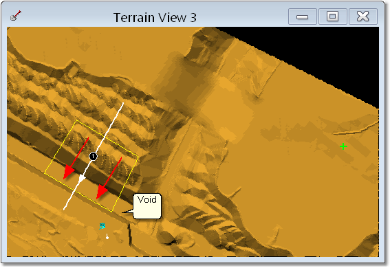
Reshaping Polygon set up for Final Void Fill.
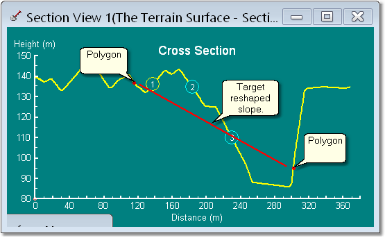
Reshaping Polygon set up for Void Fill – Cross Section View.
Note that in the above figures the Polygon extends only a small way up the highwall. If the polygon is extended to far up the highwall there is a danger that some rounding at the toe of the slope will occur resulting in a small slope oriented upwards towards the highwall. Hence the Polygon should start close to the toe of the highwall and be nudged out gradually, as necessary, as the reshaping process continues. A cross section view should be used to assess this situation. The following figure illustrates the progression from post mining topography to the completed void fill slope via a series of iterations:
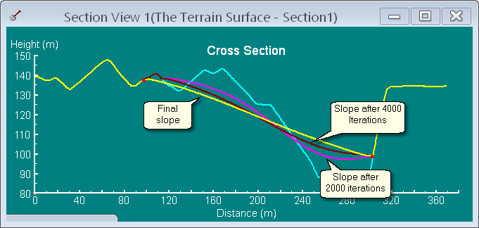
Intermediate and Final Surfaces for Void Fill Reshaping.
Effects of Reshaping Parameters.
The reshaping parameters were described in the previous topic. The relevant parameters are:
•Rarefaction Factor
•Straightness Coefficient
•Maximum Number of Iterations
•Iteration Step
In addition these resahping parameters there are two slope criteria parameters:
•Maximum Slope Criterion
•Percent of grid within maximum slope.
These two parameters determine if the reshaping stops prior to completion of the total iteration steps. Once the reshaping is initiated it will continue until it either the Maximum Number of Iterations has been completed or a proportion of slopes within the polygon, determined by the "Percent of Grid" parameter are at all less than the design slope. It is generally best to set the Maximum Number of Iterations to a smaller value such that it will take between five and 10 runs to reduce the slopes to design. The surface should be checked after each run and an additional run done if more reshaping is required. This way the initial surface will be transformed to the design slope in a gradual manner with the user regularly checking and stopping the process manually when the slope is deemed to be adequate. Setting a suitable Maximum Number of Iterations is hence very important. The amount of slope reduction which will occur for each iteration is a function of the following:
•The size of the reshaping Polygon relative to the grid spacing (i.e. the number of grid points within the polygon).
•The Slope length within the current Polygon.
•The various Reshaping Parameters, their influence is described below.
To summarise, the Maximum Number of Iterations should be set to a sufficiently small value such that with each set of iterations a modest slope reduction occurs. The user should check the slopes after each set of iterations and stop when the slopes are acceptable.
As an approximate guide for a surface gridded at the default 3 m spacing and using the default Reshaping Parameters the following numbers of iterations should produce a modest slope reduction:
•Slope length around 50 m; 50~250 iterations.
•Slope length 50m - 100m; 250 ~500 iterations
•Slope length 100m – 150m; 500 ~1000 iterations
•Slope length 150m – 200m; 1000 ~3000 iterations.
Greater slope length is then 200 m will require substantially increased iteration numbers.
 Tip – Polygon location relative to slope.
It is generally best if, using the techniques described above, the initial polygon is placed such that approximately spans the length of the final slope. Further, it is best if this polygon is initially placed slightly less than this length and its ends a draged out slightly as the reshaping progresses. This will result in straighter final slopes and minimise the possibility of excessive slope reduction.
An understanding of the influence of the Reshaping Parameters is essential to the efficient use of this software. A good working knowledge of these parameters can only be acquired through experience using the software. The following notes are intended to provide a start in acquiring this knowledge.
The Rarefaction Factor is the standard Rarefaction Factor which is used in many 3d-Dig functions. It temporarily thins the surface grid while the function is operating. In the case of Surface Reshaping factors greater than 1 result in the reshaping iterations computing far more rapidly but will result in a somewhat lower resolution surface. In reshaping parameters spoil and void fill the slope lengths and volumes can be very large requiring many iterations. In such situations it can be beneficial to start with a reduced Rarefaction Factor to get say the initial two thirds of the reshaping done, then return to full resolution to complete the task. The effects of the lower resolution I generally felt most at the toe and crest of the design slopes and in particular when reshaping a void fill scenario where the Polygon must be not too far up the highwall this can be an issue. Note that no volume inaccuracy occurs with lower resolution reshaping. In most scenarios it is recommended to either use Rarefaction Factor of either 1 or 2.
The Straightness Coefficient and controls the form of the slope produced with each set of Iterations. The reshaping algorithm will tend to morph the starting topography into a reasonably straight slope via a series of S curves. Larger values for the Straightness Coefficient will produce a tighter S curve and lower values will produce a more relaxed S curve.
The Iteration Step controls the amount of slope reduction that occurs with each Iteration. Higher Iteration Steps will produce more rapid slope reduction with a given number of iterations. However high values may lead to some distortion in the slope shape, lower values tend to produce more reliable and predictable slope shape. It is generally recommended to use the default, 0.2, value. For very large slope lengths a high value can be used initially to speed up the initial slope reduction followed by a lower value for slope completion. In some cases reducing the value to 0.1 can give better control over slope shape.
The following figure shows a post mining topography with a number of reshaped surfaces superimposed. These surfaces are the result of the same number of iterations (3000) but using different Reshaping Parameters. The surface coloured yellow is the topography and this is achieved with 30,000 iterations with a Straightness Coefficient of 4.0 and Iteration Step of 0.1 :
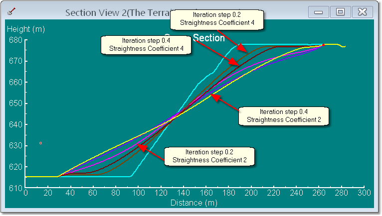
Surface Shapes After 3000 Iterations, Various parameters.