|
<< Click to Display Table of Contents >> Surface Reshaping Functionality |
  
|
|
<< Click to Display Table of Contents >> Surface Reshaping Functionality |
  
|
In order to access the spoil reshaping functionality the simulation mode must be set to Reshaping:

Simulation Mode Pulldown List - Reshaping Mode.
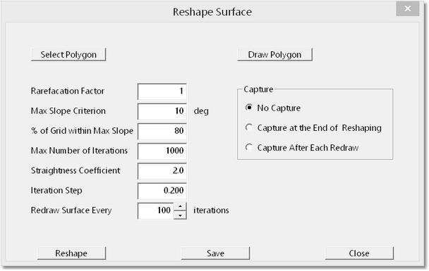
Once the Reshaping mode is selected the Reshaping dialog is accessed using the Menu command Reshaping/Reshape Surface:

Surface Reshaping Dialog.
In order to understand these parameters is important to have a basic understanding of how the reshaping algorithm works on points on the surface to perform the reshaping task. The the following describes the basic process:
The reshaping regions are delineated by placing closed Polygons. These Polygons are Surface Features with Closed status. They can be created prior to initialising the reshaping functionality using the Polygon Toolbar button, or they can be created using the Reshaping dialog.The Reshaping works on grid points contained within the currently selected Polygon. Only points within the Polygon will be modified during the current run of Reshaping. With each iteration the system looks at all grid points within the Region and establishes the surface slope at each grid point. The sum of all these individual grid point slopes is referred to as the sum of slopes. In order to reduce the overall surface slope some grid points must be depressed vertically (producing cut) and some must be raised (producing fill). The reshaping algorithm initially establishes the relative vertical movement of all points which will produce the maximum reduction in the sum of slopes for the minimum amount of vertical movement points, that is to say the surface movements which will create the maximum slope reduction with the minimum amount of earthworks. However this optimum movement of points does not necessarily balance cut and fill, so a further manipulation on the point movements is applied to ensure volume invariance(cut and fill balance).
The optimum relative movement of points described above applies to the surface at its initial state. As soon as the surface is modified by the reshaping process this optimal movement becomes invalid. To overcome this problem the reshaping is conducted in small increments. The optimum relative movement of surface points is initially established and made volume invariant, all points are moved up and down as required by small increments conforming with this relative movement. On completion the entire calculation is reapplied to determine a new optimal point movement for the now modified (partially reshaped) surface. This results in the iterations via which the reshaping takes place.
The Surface Reshaping dialog contains the following components:
Select Polygon button. When this button is selected the dialog is temporarily dismissed and the terrain cursor becomes active in the active Terrain Window. The user can select any polygon for use in the current run of Surface Reshaping.
Draw Polygon button. When this button is selected the dialog is temporarily dismissed and the terrain cursor becomes active in the active Terrain Window. The user can draw a Polygon in the usual manner. The Polygon is completed with right click and the Reshaping Dialog returns.
Rarefaction Factor. The Rarefaction Factor controls how the grid is applied for reshaping. If this factor is set to 1 all grid points within the polygon will be used in the reshaping calculation. If the factor is set to 2 a thinned grid using every second grid point is used in the reshaping. Lower Rarefaction Factors result in the calculation proceeding much more rapidly but the result has lower resolution.
Max Slope Criterion. This parameter is generally set to the target design slope. Is used in conjunction with the following parameter.
% Of grid within Max Slope. This factor refers to a percentage of the grid points within the current Polygon. If this percentage of grid points is at or below the slope specified in the Max Slope Criterion then the reshaping will cease when this condition is met. This parameter plus the Max Slope Criterion are intended to prevent the reshaping continuing beyond the stage when the surface within the polygon approximately conforms to design.
Straightness Coefficient. The Straightness Coefficient controls the form of the reshaped surface. Higher valued Straightness Coefficients tend to produce a straighter (less curved) slope. Lower values produce more of an "S" curve. Note that reshaped surface is initially tend to mimic the original surface and have an S shaped which will tend to straighten as more reshaping iterations are applied. Recommended values are between 1 and 6. Generally values in the range of 2 to 4 should be used.
Iteration Step. The above discussion of the reshaping algorithm refers to the fact that the reshaping must be conducted in small increments, as the optimum movement of points which is calculated only applies to the current state of the surface. The size of these it increments is controlled by the Iteration Step. Increasing the size of the Iteration Step will increase the amount of slope reduction which is produced by a given number of iterations. However increasing this number excessively can produce instability. In addition higher numbers for this parameter can produce undesirable shapes in the reshaped surface. Values in the range of 0.2 and 0.6 are recommended.
Redraw Surface Field. During the reshaping process the terrain surface is refreshed intermittently to update the user on the current state of reshaping. The user can key the Escape key at any time and end the reshaping. The Redraw Surface field controls how many iterations are performed before the refresh is conducted. This number refers to the number of iterations which are performed before a surface refresh is performed.
Capture group. The radio buttons in the Capture Group control screen capture of the reshaping process. When the various capture options are selected files will be saved creating a slideshow of the reshaping process. The folder in which the files are saved and other details are set using the main menu Options/Capture Settings.