|
<< Click to Display Table of Contents >> Setting up a Dump Template |
  
|
|
<< Click to Display Table of Contents >> Setting up a Dump Template |
  
|
To perform dump simulation the first task is to set up to Dump Template. The Dump structures described above (point line and area) belong to a Dump Template. The Dump Template contains all the constraints that control the behaviour of the dump. Any number of Dump Templates and associated dump structures can be present in the 3d-DigPlus file.
To set up a new Dump Template click on the Dump Settings toolbar button:
Dump Settings Toolbar button.
This will open the Dump Settings dialog:
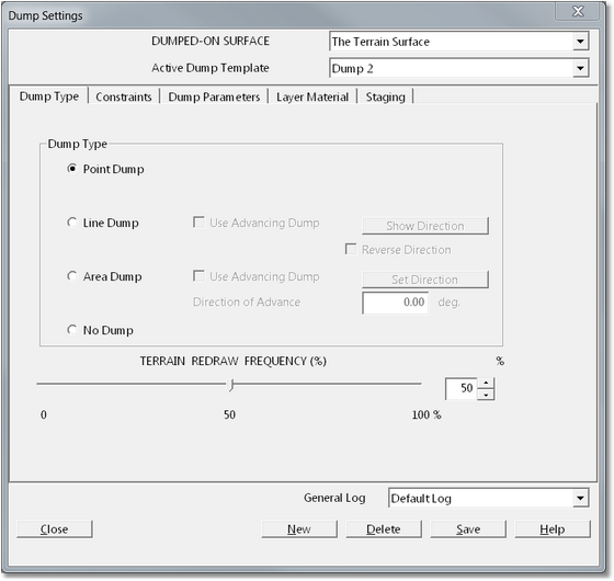
Dump Settings Dialog.
The Dump Settings dialog contains the following general items:
Dumped on Surface pulldown list (top of page). This list contains a list of all Surfaces in 3d-DigPlus file. Typically dumping takes place on the Terrain Surface. However 3d-DigPlus does allow for dumping on any surface and each template is associated with a particular Surface. In almost all situations you will be done on the terrain surface therefore the Dumped on Surface should be the Terrain Surface.
Active Dump Template pulldown list (top of page). This pulldown list contains all currently existing Dump Templates. The Active Dump Template is the one which will be used the next on the user initiates a dumping operation. It is also the Dump Template which will be subject to editing in the Dump Settings dialog.
General Log pulldown list (bottom of page). This pulldown list contains a list of all General Material Logs. The Material Log selected with this pulldown list will be the log from which material will be dumped with the selected Dump Template.
Control Buttons ((bottom of page). These buttons are at the very bottom of the dialog and allow the creation, deletion and saving of Dump Templates.
The Dump Settings dialog contains five pages. The dialog opens on the Dump Type page.
The Dump Type Page contains the following items:
Dump Type Group. The Dump Type Group consists of four radio buttons for the selection of the Dump Type together with various buttons and fields that allow associated parameters to be defined. Note that the Dump Type can be specified by selecting one of the items in the Dump Type group, however it can also be automatically specified when the dump object (point, line or area, is created. The Dump Types and associated parameters are:
•Point Dump. The Point Dump consists of a single point and no additional parameters are required for its definition.
•Line Dump. The Line Dump consists of a line. The line can be a straight two point line or multi segment line. When a Line Dump is used in its default mode material is dumped continuously along the entire line until either the contents of the Material Log are empty or some constraints are met. The Line Dump type has the option of Advancing Dump. Advancing Dumps are used in conjunction with a level or surface constraint. The Advancing Dump will start dumping material at one end of the line until the constraint is reached and then continue dumping an advancing direction toward the opposite end of the line. The video clip at the end of this section illustrates Advancing Dumps. The Line Dump option includes a button titled Show Direction and the checkbox titled Reverse Direction. These allow the direction of the advancing dump to be displayed in the Terrain Window and the direction to be reversed. Advancing Line Dumps are illustrated in the video clip at the end of this section.
•Area Dump. The Area Dump consists of a closed, multisided polygon. Material is dumped within the polygon. Material will be dumped within the nominated area until either the active Material Log is empty or some constraints have been reached. The Area Dump type includes the option of Advancing Dump. Advancing Dumps are used in conjunction with a level or surface constraint. When Use Advancing Dump is selected the associated Set Direction button becomes active. When the Set Direction button is clicked a Dump Settings dialog is temporarily dismissed and focus returns to the Terrain Window. the Direction tool becomes active which allows the user to define the dump direction. Once the direction is defined focus returns back to the Dump Settings dialog.When the Advancing Dump commences material is dumped at the start and end and built up until the constraint is reached, it then advances out in the nominated direction. the use of the Advancing Area Dump is illustrated in the video clip in the previous section.
•No Dump. Selecting this option removes any pre-existing dumps associated with the template.
Terrain Redraw Frequency group. This group includes a slider bar and field to define a parameter called Terrain Redraw Frequency. As dumping simulation proceeds the terrain in the vicinity of the dump is regularly refreshed to display the developing dump. the Terrain Redraw Frequency parameter determines how frequently the terrain is refreshed.
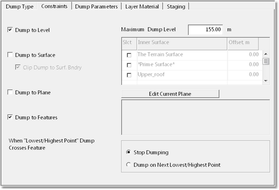
Dump Settings dialog, Dump Constraints page.
The Dump Constraints Page contains the following items:
Dump to Level checkbox and Maximum Dump Level field. These items control the Dump to Level constraints. When the Dump to Level checkbox is selected dumping will continue until the RL of the top of the dump reaches the level specified in the Maximum Dump Level field.
Dump to Surface group. The Dump to Surface group consists of the Dump to Surface checkbox, the Clip Dump checkbox and Surface List. When the Dump to Surface checkbox is selected the the Dump to Surface constraint is switched on and the Surface List becomes enabled. The Surface List contains a list of every surface in the 3d-DigPlus file together a checkbox. Any surface whose checkbox is selected will be enabled as a constraining surface. If multiple constraining surfaces are selected all surfaces will act as constraints will act in parallel. The resultant dump surface will be the intersection of all Constraining Surfaces. The Clip to Surface Boundary checkbox is selected by default. This ensures that no dumping will occur outside the bounds of any selected Constraining Surface. The surface list also includes an offset parameter for each surface. This offset can be positive or negative and results in a dump constraint being offset by the specified distance.
Dump to Plane Group. The Dump to Plane Group consists of the Dump to Plane checkbox and the Edit Current Plane button. Selecting the Dump to Plane checkbox enables the Dump to Plane constraint. The Current Plane surface will be used as a dump constraining surface. The Edit Current Plane button provides a shortcut access to the Set Current Plane dialog. For more information on setting up Current Plane see the Current Plane topic.
Dump to Features group. This group controls the Dump to Features constraint. Dump Limit Features are line string constraints placed on the topography using the Add Dump Limit Feature function. Once a Dump Limit Feature has been created and is enabled in the dump template material from the dump is constrained from flowing across the Dump Limit Feature. the Dump to Features group contains the following elements:
•Dump to Features checkbox. When this checkbox is selected the Dump to Features constraint is enabled.
•Dump Limit Features list. The Dump Limit Features list contains a list of all Dump Limit Features into 3d-DigPlus file as each Dump Limit Feature is added it is given a unique number and these numbers appear in the list.Each Dump Limit Feature in the list has an associated checkbox, selecting the checkbox enables a particular Feature. Multiple Dump Limit Features can be selected in parallel.
•Initial Constraint Met options. The Initial Constraint Met options consist of two radio buttons . Stop Dumping and Dump on Next Lowest Point. These two buttons control how the system responds the first time a parcel of dumped spoil meets a limit feature. If the Stop Dumping checkbox is selected dumping will cease at this time. If the Lowest Point option is selected the system will search for other points within the dump on which material can be complete without violating the limit feature. The Next Lowest Point option is the default setting and is the one that is required in nearly all instances.
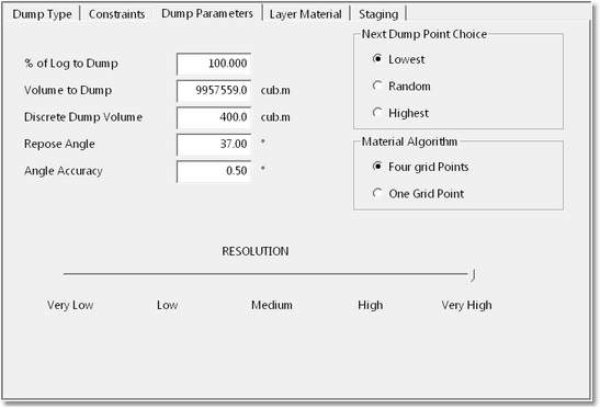
Dump Settings Dialog, Dump Parameters page.
The Dump Parameters Page gives access to parameters to control the operation of the dump algorithm which models the dumping process. The Dump Parameters Page contains the following items:
% of Log to Dump field. This field controls the proportion of the active Material Will which will be dumped. By default this parameter is set to 100% resulting in all material being dumped. the user can optionally set a lower percent dumped and dump only a portion of the log contents.
Volume to Dump. This is the volume in the contents of the Active Log. Note that this volume is not relevant when dumping is conducted as part of a simulation.
Discrete Dump Volume. The Discrete Dump Volume is the volume of material in each individual parcel of dumped. This is an important parameter which needs to be optimised for each application. A small discrete volume will generally give a more finely resolved dump. Large a discrete volumes will were generally result in the material being dumped more rapidly.
Repose Angle. The Repose Angle parameter controls the the gradient on the surface of the result Dump.
Angle Accuracy. The Angle Accuracy parameter controls the accuracy with which the Repose Angle parameter is achieved in the file spoil pile. A smaller Angle Accuracy parameter will result in the gradient on the surface of the resultant Dump being very close to the specified Repose Angle. However a small Angle Accuracy parameter can result in longer dump simulation times.
Next Dump Point Choice group. In the case of Line and Area dumps there is a choice of many points along the line or within the area on which the next parcel of material can be dumped. The Next Dump Point Choice group sets the rules used to determine which point the next parcel will be dumped. The options (controlled by radio buttons) are:
•Lowest. The Lowest method results in the next parcel being dumped on the lowest (elevation) point along the line or within the area. Once a parcel of spoil is dumped on the lowest point it's elevation increases as a consequence of the dumping. The system then reassesses the next lowest point and dumps the next parcel. This method results in a dump building up from the lowest point on the topography within the dump. It is generally the best option for most purposes.
•Random. The Random method chooses points on which to dump at random (along the Dump Line or within the Dump Area). This method results in a dump of even "thickness" being built up on the topography.
•Highest. This method chooses the highest point to dump the first parcel of material. This method has some use in conjunction with level constraints but is not to be used for unconstrained dumping.
Material Algorithm. The Material Algorithm parameter controls how each parcel of material is dumped onto the topography. The Four Grid Point option places the parcel within the four nearest grid points and generally produces the most satisfactory results. The One Grid Point option can produce more accurate results in some circumstances.
Resolution Slider bar. The Resolution Slider Bar controls the Dump Resolution. The default setting is Very High, which results in dumping taking place on the full surface grid model. As the resolution is reduced the grid on which material is dumped is progressively thinned. If the resolution is reduced to High every second grid point will be used. Reducing the resolution can greatly increase the speed of dumping and hence reduce simulation times. Reducing the resolution does not affect the volumetric accuracy of the resultant dump. However it does reduce the accuracy of the resolution of the dump surface shape. This can result in less material fitting into a given dump than will occur at full resolution. It is possible to dump the bulk of material at low resolution and conduct another run of dumping at full resolution.
The process of repose angle dump simulation is very compute intensive and large dumping simulations can take several minutes to complete. The speed of simulation depends on many factors but the most significant are:
•Dump Resolution
•Terrain Redraw Frequency
•Terrain Redraw speed. This is function of the Terrain Surface grid spacing and the Fast Draw settings.
To achieve fast dumping it is recommended that the Dump Resolution is reduced,and that the Fast Draw setting Used Thinned Grid is enabled. For very large dumps reducing the Terrain Redraw Frequency also help. Modest sized dumps should dump rapidly even with full Dump Resolution and full Terrain Resolution. Is only for very large dumps at these settings need to be modified.
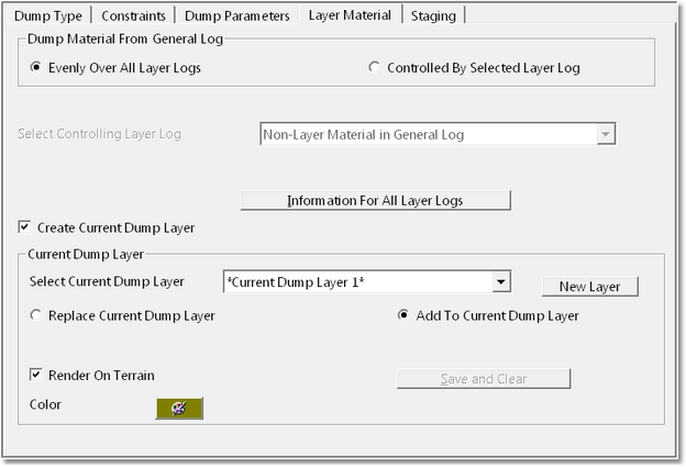
Dump Settings dialog, Layer Material page.
The Layer Material page that controls two quite distinct Layer related processes:
•Layer Log Dumping. When Layer Logging is implemented material excavated from a specific Layer will report to And associated Layer Log. General Logs and Layer Logs operate in parallel; all excavated material reports initially to the General Log and, if Layer Logs are set up, is subdivided (in parallel) to any nominated Layer Logs. Material in any General Log thus contains material which belongs to Layer Logs. The following figure illustrates this:
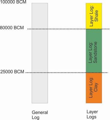
Relationship between General and Layer Logs.
In the above figure the General Log contains 100,000 BCM of material. Three parallel Layer Logs contain the same material logged according to the Layer from which they originated. When material is dumped it is always dumped from the General Log. When Layer Dumping is implemented the Layer Log Volumes are used to restrict the dumped volume. If the material shown in the figure above was dumped using the Clay Layer Log, 25,000 BCM from the General Log will be dumped and the contents of the Clay Layer Log will go to zero.
Key Information - Layer Dumping
 Note that Layer Logging and Layer Dumping were initially established in an early version of 3d-DigPlus. In the current version the processes available in Automated Excavation and Dump sequencing generally provide a superior means with which to achieve the same ends.
•Dump Layer Creation. Dump Layer creation allows a Layer to be created to contain material within the Dump. As material is dumped the system creates and constantly updates a roof and a floor surface for the dump. These roof and floor surfaces are then used to construct a Layer which is usually set to render on terrain and thus the dump is produced with a distinctive colour.
The Dump Settings Dialog Layer Material Page consists of two groups:
Dump Material from General Log group.
The Dump Material from General Log group establishes whether or not Layer Log dumping is implemented. The Group contains two radio buttons:
Evenly over all Layer Logs. If this option is selected any Layer Logging set up will be ignored and material will dump from the General Log unrestricted.
Controlled by Selected Layer Log. If this option is selected the adjacent Controlling Layer Log pulldown list is enabled. This pulldown list contains a list of all Layer Logs in the 3d-DigPlus file. When a particular Layer Log is selected material dumped from the General Log will also be dumped, in parallel, from the Layer Log. Thus the total volume dumped will be restricted to the volume in the contents of the selected Layer Log.
Create Current Dump Layer group.
When the Create Current Dump Layer checkbox is selected a layer, consisting roof and floor surfaces and Layer will be created to model the dump.
The Create Current Dump Layer group contains the following items which must be set up to produce an appropriate Dump Layer:
Current Dump Layer pulldown list. This pulldown list contains a list of all Layers in the 3d-DigPlus file. If a layer is selected from this list it will be used for the Current Dump Layer. If this layer already has a roof and floor surface these will be extended by the dump modelling. Generally only layers which have been specifically created for dump modelling are selected used in this manner.
New Layer button. Clicking the New Layer button will create a new vacant Layer for use in modelling the active Dump. When setting up a new dump, creating a new specific dump Layer in this manner is the usual procedure.
Replace/Add to Current Dump Layer radio buttons. These radio buttons control the permanency of the Dump Layer created. The options work as follows:
•Replace Current Dump Layer. If this option is selected a dump layer will be created when material is dumped with the Active Dump Template. As material is being dumped the coloured dump will appear on the topography and will remain when the dump is complete. However when the Dump Template is used a second time to dump material the previous Dump Layer will be replaced by a layer for the material recently dumped. When this method is implemented and a animation produced for the design, only the advancing portion of the dump will appear coloured.
•Add to Current Dump Layer. If this option is selected a dump layer will be created when material is dumped with the Active Dump Template. As material is being dumped the coloured dump will appear on the topography and will remain when the dump is complete. When the Dump Template is used a second time, the Dump Layer from the previous instance will remain and the currently dumped material will be used to extend the current Dump Layer. In this manner all material dumped with a particular Dump Template will report to the same Dump Layer.
Save and Clear button. When this button is clicked the dump layer associated with the active Dump Template will be permanently saved. The user is presented with a dialog allowing the name of the Layer, the Roof and the Floor to be input. If Layer Dumping is used to gain with this Dump Template a new Dump Layer will be created.
Render on Terrain checkbox. If this checkbox is selected the layer will appear rendered on the terrain. This checkbox is on by default.
 Tip - Dump Layers
The layers created by Layer Dumping are standard 3d-DigPlus Layers. They consist of a roof Inner Surface, a floor Inner Surface and a Layer structure. The Layer can be edited in the same manner as other Layers using Terrain/Surface/Layers. The Roof and Floor surfaces can be used or exported as with any other Inner Surfaces.