|
<< Click to Display Table of Contents >> Dump Simulation Principlers |
  
|
|
<< Click to Display Table of Contents >> Dump Simulation Principlers |
  
|
Dump modelling creates spoil dumps by modelling the rilling action of dumped material. Material from the active log is dumped onto the topography in a series of discrete parcels. This dumping process continues until the volume in the log contents is exhausted, or until some constraint is reached. The figures below illustrate this process:
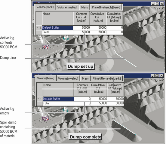
Dump Modelling.
Each discrete parcel of dumped material is placed on the topography and allowed to rill out at the repose angle. The region of the topography onto which the material is placed is specified by creating a dump.
Once a dump is created, it is a permanent (until deleted) part of the design file. Such a dump can be moved and reapplied. Like excavation polygons, dumps are associated with a Dump Template that controls their behaviour.
There are three different types of basic dumps: point, line and area. These are shown in the figure below:
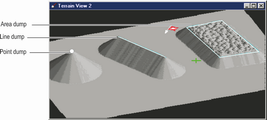
Dump Types.
Material is dumped onto the topography at a repose angle that you can specify. This repose angle is an important dump modelling parameter. Its value depends on material properties and the type of dumping action being modelled.
3d-DigPlus identifies an individual grid point within the defining dump structure (point, line or area) on which the next discrete parcel will be dumped. You can set a number of parameters that guide 3d-DigPlus in its selection of this point from the set of all other possible points located within the dump. Typically, this is the lowest point.
The nominated discrete parcel is dumped on the next grid point and the terrain model updated. This process is repeated until the active log contents are empty or a constraint is reached. The terrain view in the active window is updated regularly throughout this process. The dumping execution can be halted at any stage by keying the “Esc” key or pressing the right mouse button.
All dumps, be they point, line or area, are associated with a dump template. The dump template contains all the settings and constraints that control the dump behaviour. You must create a suitable dump template and set the appropriate constraints and settings before you can create a dump.
Once a dump is created it becomes a permanent part of the design file, and it can be moved, reapplied and edited repeatedly. Multiple dumps may be present in a design.
Dump constraints
The dump structure (point, line or area) controls the planar extents of the region on which material can be dumped. However, as occurs in reality, dumped material can rill out well beyond the point on which it was initially placed.
If a modelled dump is executed without constraints, the entire contents of the active log will be dumped within the dump structure. The resultant spoil pile will extend vertically and horizontally as far as required until the volume in the log is exhausted.
In practice, dumps are typically constrained by machine limits, as well as by planar and vertical constraints. 3d-DigPlus provides a variety of dump constraints to accommodate these requirements. The dump constraints are illustrated in The figure below. This figure illustrates the effect of various constraints on each of the three dump types (point, line and area):
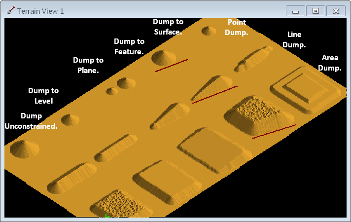
Dump Constraint Types.
The dump to level constraint will allow the dumping process to continue until the specified level is reached. Dumping will continue as long as there is a candidate point for dumping that is below the specified height limit.
For point and line dumps, when the last parcel is dumped on a particular point, its height will be below the limit height prior to dumping. The last dump parcel may raise the height above the limit. The final height will be very close to the limiting height if the parcel size is small. For an area dump that is level-limited, the resultant dump top will conform exactly to the limiting horizontal plane.
The dump to plane constraint allows the user to define a plane that is used to constrain the dump process. The dump to plane works in exactly the same manner as dumping to a level, except that it allows users to specify an inclined plane as the height constraint.
Any defined inner surface can be used as a dump constraint. This type of constraint is referred to as a dump to surface constraint. Its behaviour is similar to that of a level or plane constraint. As the dumped material of an area dump reaches the surface level at any point it is modified to conform to the surface shape. Incrementally building a truck dump to a predetermined form or constraining a dump to a long-term final landform surface are examples of the use of the dump to surface constraint option.
It is frequently necessary to limit the planar extent of a spoil dump. Preventing spoil from rilling out onto a haul road or back into a pit are examples of this. This is done using the dump to feature option. The user can define constraining features that allow material to rill out from a dump and advance up to these features. Dumping ceases on those parts of the dump, which cause material to reach the constraining feature. The effect is that a dump is controlled in such a way that material will not to go beyond the constraining feature. Any number of constraining features may be used to limit the dumping process.
When the Line and Area dump types are used in conjunction with a level or surface constraint, Advancing dump mode becomes available. With the Advancing dump an additional parameter, Dump Direction is specified. Dumping commences at one end of the dump (line or area) and builds up until the constraint is reached at this point. Dumping advances out along the dump in the specified Dump Direction. The following video clip illustrates when when Advancing Dump:
Staged Dumps
Staged Dumping allows a dump to be built up by lifts and passes. This is similar to the manner in which large truck dumps are typically constructed. Staged Dumping is described in the following topic Creating Staged Dumps.
A Layer can optionally be created as part of the dump. When the Layer Dump option is selected as the dump is modelled a roof and floor surfaces for the dump Is created and other layer is formed using this roof and floor. The layer can optionally be rendered on terrain allowing colour coded dumps. The system can also be used to build stratified dumps consisting of several layers. The following figure illustrates Layer Dumping:
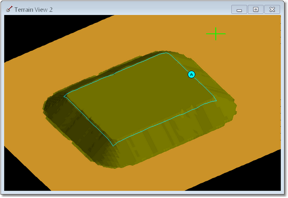
Dump modelled with Layer Dumping enabled.
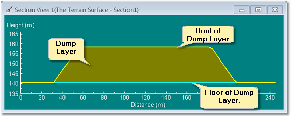
Cross section through layered dump.