|
<< Click to Display Table of Contents >> Data Input |
  
|
|
<< Click to Display Table of Contents >> Data Input |
|
3d-DigPlus requires a large body of data to model a mining process. These data may be imported from external sources such as survey data, manually keyed in, or generated by the system.
3d-DigPlus provides for import of the following types of data:
Topographic data. These data, such as the terrain, coal seam roofs and floors, pit surfaces (benches and pit outlines and spoil dumps), are used to model three-dimensional (3D) surfaces. Raw topographic data contain spot heights and terrain features. Spot heights are random 3D data points and terrain features are 3D line-strings. Terrain features perform the function of break lines in a conventional DTM system.
Three-dimensional CAD line-strings. CAD line-strings are used to designate pit and spoil toes, crests of road alignments and other earthworks design elements. They are imported into 3d-DigPlus as Surface Features. These may appear on surfaces modelled in 3d-DigPlus. They may be “snapped to” for design purposes. Surface features do not contribute directly to the topographic model of a surface.
Key Information - Terrain features and Surface Features
 Terrain features are an active part of the underlying DTM of a surface. They form part of the triangulation and hence affect the surface model. Terrain features can only be viewed in a data window.
Surface features are a passive design elements and do not affect the terrain triangulation. Surface features may optionally be viewed in a rendered or frame terrain window, and may be used as design aids. Surface features do not have independent elevations but acquire their heights from the surface on which they are “draped”.
Although these two types of features have quite different functions, they share a common structure and 3d-DigPlus allows you to copy features from the data to the surface and vice versa.
Machine parameters. 3d-DigPlus requires considerable information on a machine’s geometry and mechanical characteristics to model the machine performance. A comprehensive interface is provided for the input of these data. Once a machine has been set up in 3d-DigPlus, its characteristics may be saved to a file and imported into another 3d-DigPlus file via the machine file type.
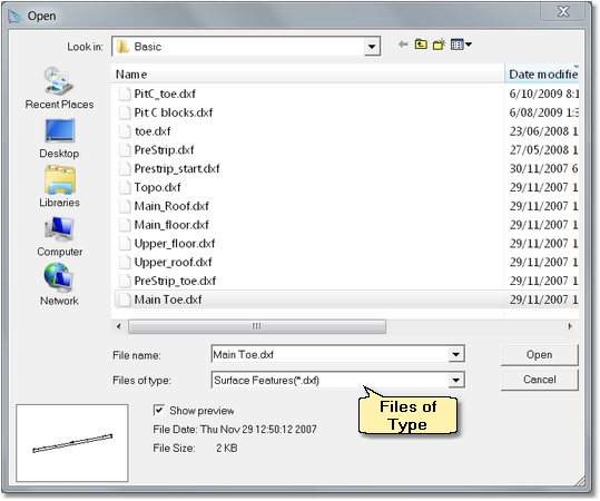
The first data to be loaded is always the Terrain Surface and this is typically imported as DXF objects. From the Main Menu the option File/Import is selected. This will open the File Import dialog box. From the Files of Typed pulldown list the option Terrain Data (*.dxf) is selected:
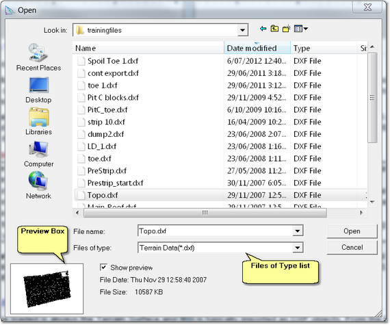
All DXF files in the folder will be displayed. The appropriate file is selected and image of the data is presented in the Preview Box.
Occasionally the data may be exported from the host system with erroneous zero values for some Easting and northing coordinates. This creates a very large span of data in either the East or North direction. In such cases Preview Box will normally appear empty apart from two small dots. Such data should not be further processed and the original data should be re-exported from the host system.
When the appropriate file is selected the Open button is clicked. The Select dxf Layers dialog box will be produced:
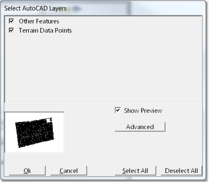
Data exported from the host system will often be contained in several layers within the DXF file. In such cases these layers appear in the Select dxf Layers dialog box and may be selected or deselected. By default all layers are selected and typically all layers contain valid topological data and must be imported.
In some cases some layers may contain non-topological data. De-select the checkbox associated with these layers. Once deselected the data will be removed from display in the Preview Box.
The Select DXF Layers dialog box includes and Advanced button. Clicking the Advanced button opens the DXF Objects dialog box:
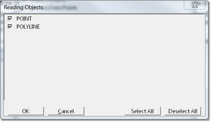
On occasions a DXF file may contain non-topological data which is not specifically contained in a particular dxf layer. Frequently such data will be of a particular object type which is not typically used for topological data. In such cases this data may be filtered out using the advanced settings and deselecting the inappropriate object type.
Note that 3d-DigPlus has no way of identifying topological and non-topological data. The data file should ideally contain only topological data.
Once the appropriate filters are selected the data are imported and 3d-DigPlus produces a Data Window to display the imported data:
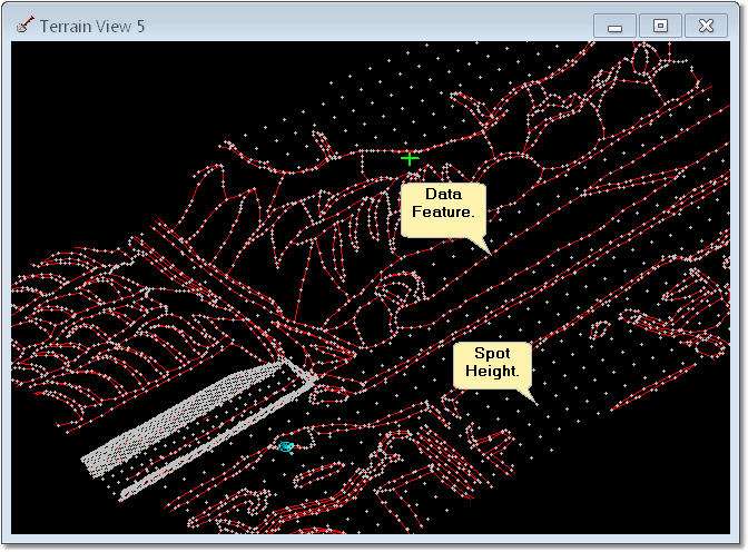
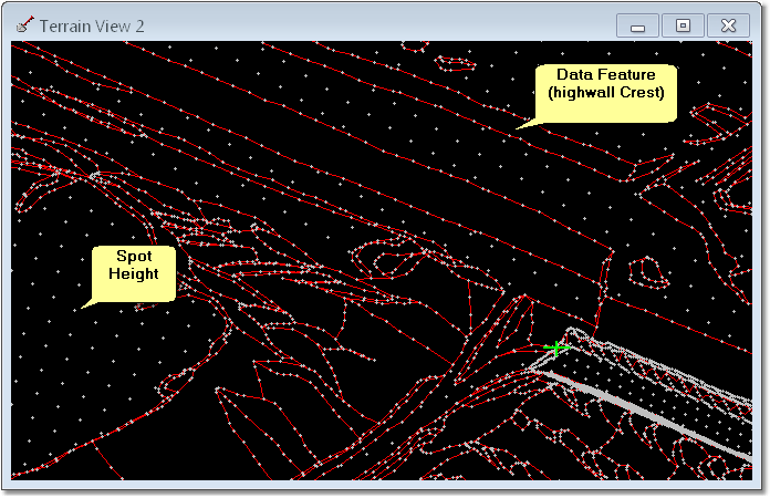
There are two types of topological data elements, Spot Heights and Data Features.
Spot Heights are individual data points. Surface Features are linear elements. Data Features function as Break Lines in the triangulation. Triangles are not allowed to cross these brake lines. Crest lines such as highwall am spoil crests are typically modelled as Break lines and will import as Data Features into 3d-DigPlus. The following figure illustrates Spot Heights and Surface Features as they appear in the Data Window:
All topological surfaces other than the Terrain Surfaces are referred to as Inner Surfaces. Typically Inner Surfaces are imported from DXF files, the following description assumes that the surfaces are loaded from a DXF file. There are two modes of import for Inner Surfaces:
1.Individual Surface import.
2.Multi-Surface import.
Method one involves selecting one DXF file at a time for import. Method to involves selecting a group of DXF files, all of which are to be imported as Inner Surfaces, and importing all surfaces in one operation.
Individual Surface Import.
When using the individual Inner surface import option the Surfaces are imported from file one at a time. The import process must be repeated as many times as there are files (Surfaces) to be imported.
Many functions and operations in 3d-DigPlus produce a Surface list. The order in which Inner surfaces appear in this list is initially the order in which they were imported. Where large numbers of Inner Surfaces exists it is important, for legibility, that these Surface lists have a logical order. Geological surfaces should be ordered from the highest level surface down. Design Surfaces should appear either before or after the geological Surfaces and should be arranged in an order that is legible to the user. Consequently the required order should be considered in advance and the Surfaces should be imported in this order. If some surfaces appear out of sequence they can be re-ordered using the Terrain/Surfaces/Edit command. This is explained in the following topic Loading Multiple Inner Surfaces.
The procedure for loading Individual geological and design surfaces is the same as for terrain data except the option Inner Surface (*.dxf) is selected from the Files of tight pulldown list on the File Import dialog box:
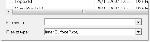
All surfaces other than the Terrain Surface are referred to as In a Surfaces. As terrain data are only loaded once and Inner Surfaces are loaded frequently, the Files of type defaults to Inner Surface.
Once a DXF file is selected the Layer Select dialog is produced. Depending on how poor data were exported from the host system, the DXF file may have Layers containing non-topological data (e.g. lease boundaries). The Layer Select dialog allows the user to select those layers which will be imported. The figure below shows the Layer Select dialog:

Layer Select Dialog.
The Layer Select Dialog contains a list of all Layers with a checkbox for each layer. By default all Layers are checked, uncheck those layers which are not to be imported.
Once the desired Layers are selected the New Inner Surface dialog is produced. This dialog allows the surface being imported to be given a name which will appear in 3d-DigPlus file. The default name is the name of the source DXF file, this name can be changed if desired:
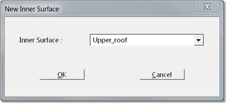
The default name appearing in the Inner Surface field is the name of the source DXF file. This field is editable and the name can be overridden if necessary.
Loading Multiple Inner Surfaces.
The process for loading multiple Inner Surfaces is similar to the process for loading individual Inner Surfaces. The Multiple Inner surface option allows multiple DXF files to be selected and loaded in one process.
As discussed in the previous topic, many functions in 3d-DigPlus produce a Surface list. It is important that Inner surfaces appear in this list in a logical order. When multiple Surfaces are imported they will initially appear In at the order determined by the window "sort by" setting. This will typically be alphabetically or by date . Consequently when the Multiple Inner Surfaces option is selected this will usually require some post processing using the Terrain/Surfaces/Edit command to reorder the surfaces.
Multiple Surfaces are imported by using the command File/Import Multi-Files. This will open the Import Surface firelight in Multi-Surface mode:

File Import Filer, Multi-Import Mode.
In this mode Files of Type list is limited to the Inner Surface(*.dxf) file type. One or more DXF files can be selected using shift click and control click. In the above figure a total of six DXF files are selected. Four of these files are coal seam roof and floor, one is a pre-strip horizon and one is a pit shell. The files in this example are sorted by name. Once the desired Files are selected the Open button is clicked. Following this the Layer Select dialog and The New Inner surface dialog are produced in turn for the first selected DXF file. Once this first file is processed this process is repeated for each other selected file.
Reordering Inner Surface
Most functions which access Inner Surfaces have an interface which produces a list of Surfaces. The figure below illustrates a typical Surface list:

Typical Surface List.
Complex designs can involve large numbers of coal seams and multiple strips. It is important that the Inner Surfaces appear in the Surface lists in a logical order. Geological Surfaces should appear in order from top (highest surface) down, strip design Surfaces should appear in the strip order and other miscellaneous Surfaces should be grouped together.
After initially importing the Inner Surfaces they are typically not in the desired order. To reorder surfaces use the command Terrain//Surfaces/Edit to open the Edit Surfaces dialog. In the top right hand corner of this dialog is the Reorder Surfaces button:

Edit Surfaces Dialog, Reorder Surfaces button.
Clicking the Reorder Surfaces button opens the Reorder Surfaces dialog:

Reorder Surfaces Dialog.
To change the position of a Surface in the list, click on the Surface to select it then use the Up Down buttons to reposition the Surface.
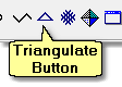
Once topological data and imported into Surface to surface must be triangulated and gridded to create the surface model. To commence this process click on the Triangulate Toolbar Button:
This will open the Triangulate dialog box:
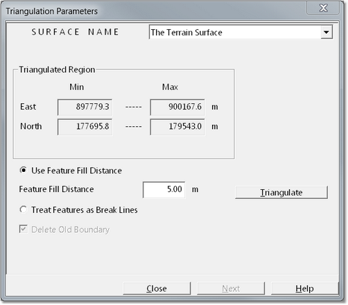
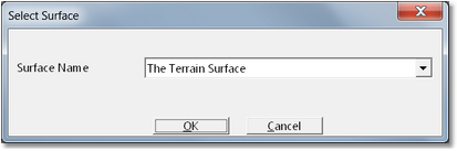
At the top of the Triangulate dialog box is the Surface Name pulldown list. It is a surface which appears in this list that will be triangulated. Generally the default surface will be the appropriate surface to triangulate. However it is important to check this pulldown list to ensure that the surface which appears is the one which requires triangulation.
The Triangulate dialog box contains a group titled Triangulate Region. This displays the minimum and maximum eastings and northings in the data set.
There are two radio buttons:
•Use Feature Fill Distance.
•Treat Features as Break Lines.
These radio buttons relate to the way Data Features (break lines) are treated in the triangulation process. By default 3d-DigPlus uses a specialised algorithm to model break lines referred to as Feature Fill Distance. This method is fast and reliable and is consequently default option. Conventional break line triangulation is performed when the Treat Features as Break Lines radio button is checked.
When the appropriate settings are established the Triangulate button is clicked in the triangulation is performed. This process should not take more than a few seconds even for large datasets.
When the triangulation is complete the Next Button at the bottom of the Triangulation dialog box will be enabled. Clicking this button will open the Grid dialog box:
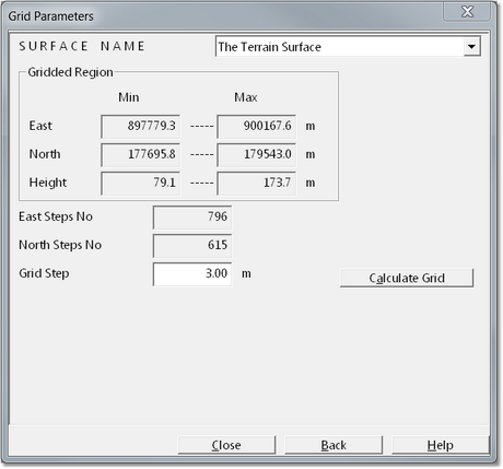
The key parameter to be input into the Grid dialog box is the Grid Step spacing. When a Grid Step spacing is input the East Steps number and North Steps number fields are adjusted to reflect the Grid Spacing selected. Note that the finer the grid spacing the larger will be the file size and speed of dumping simulation will be reduced.
Key Information Grid Spacing.
 3d-DigPlus requires a grid model to perform the dumping simulation. The grid modelling system used is highly efficient allowing large areas to be gridded at fine grid spacing resulting in negligible volume error.
When processing the Terrain Surface the user must specify the grid spacing. Smaller spacing will result in a more finely resolved surface but also result in large file size and slower dumping simulation. The appropriate grid size depends on the application it is typically in the range of 2.5 to 7 m. Inner Surfaces do not have to be manually triangulated and gridded by the user. The first operation requiring triangulated or grid model for a Inner Surface will result in that surface being automatically triangulated and gridded with a 3.0 m grid spacing. The default 3.0 m grid spacing can be modified using the Terrain/Editor Settings. Grid spacing also critically affects the refresh time for rendered windows. Options exist to optimise rendered windows such that the window is rendered at a West End grid spacing. These options are covered in the topic Optimising Display.
Once data are imported into surface, and the surface is both triangulated and gridded, two models exist to the surface a triangulated irregular network model (TIN), and a grid model. As the source data is nearly always in the form of irregular data, the triangulated model is required initially to create a surface from this irregular data. In order to perform dumping simulation 3d-DigPlus requires a grid model. Once a grid model exists further work to be conducted using only this grid model and the triangulate of model together with the source data can be deleted. However some functions will use the triangulated data if it is available on it is generally best to keep this data. Procedures forward deleting triangulation is an surface data are described in the following topic Surface Utility Functions.
Sometimes topographic and geological data for an individual surface, is contained in several individual DXF files. Loading the data for such a surface involves repeatedly loading the constituent DXF data files. By default 3d-DigPlus deletes any existing data in a surface when the user imports and new data into that surface. If a particular surface is to be built from data contained in two or more DXF files the default setting needs to be changed. To effect this change select from the main menu Terrain’Editor settings. This opens up the Terrain Editor Settings dialog:
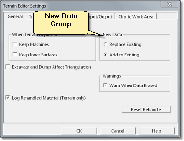
On the General page is the New Data Group. The New Data Group consists of two radio buttons, Add to Existing and Replace Existing. The default setting, Replace Existing will delete any pre-existing data in a surface when new data are imported. The Add to Existing setting will add any newly imported data to any pre-existing data. Other settings and functions in the Terrain Editor Settings dialog are explained in the following topic Surface Utility Functions.
When Terrain data are initially loaded, as described above, 3d-DigPlus automatically opens a window displaying the raw data which has been imported. This is the only instance when 3d-DigPlus automatically opens a window. This is typically when the user requires a window to display surface in a particular mode this window must be manually generated. The procedures for setting up and modifying windows are described in the following topic Setting up Windows only a basic window set up is described here.
The window initially generated is a data window, generally work is conducted in a window displaying a solid rendered view of the surface.
Windows are generated and modified via the menu item Terrain/Window Appearance or via the Window Appearance toolbar button:
This produces the Window Appearance dialog:
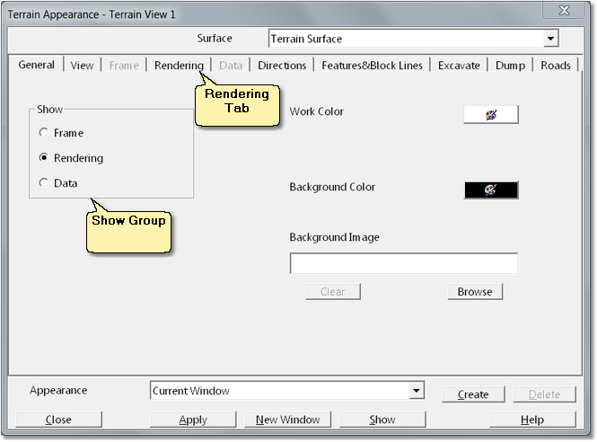
To create a window displaying a rendered view select the Rendering radio button in the Show Group on the General page. Next click on the Rendering tab (see figure above). This will display the Rendering page:
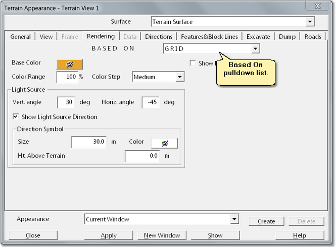
Most of the settings on this page are self-explanatory. At the top right of the page is the Based On pulldown list. The rendered view of the surface can either be based on the triangulated model or the grid model. As simulation (excavation and dumping) is only conducted owithn the grid model it is important that this option not selected unless the user has a particular need to view the triangulated model. The setting defaults to Based On Grid. If a Particular Window Presents a Rendered View Which Is Based on the Triangulation, Excavation and Dumping Will Not Appear in This Window.
When the changes to settings are complete the user can click either the Apply button or the New Window button, both located on the bottom of the dialog box. Clicking Apply will replace the display in the active window with the new settings, clicking New Window will leave the existing window in place and create a new window with the new settings:
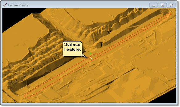
Conducting a pit design requires the importation of a variety of data. Amongst these are design lines which define and delineate objects such as crests, toes benches etc. Such design lines are referred to in 3d-DigPlus as Surface Features. Surface Features are normally imported via DXF files. When a file containing design lines is imported as Surface Features the user nominates a surface on which to load these Features and this is typically to Terrain Surface. Surface Features can be loaded onto either the Terrain or any Inner Surface. When Surface Features are imported onto a particular Surface, they will appear draped on the surface in any window presenting are rendered view of the surface. Surface Features can be modified in various ways and these procedures are described in the following topic Surface Feature Functions.
To import Surface Features select File/Import from the main menu. In the import dialog box select Surface Features (*.dxf) from the Files of Type list:
Note that when the Files of Type is set to Surface Features (*.dxf) all DXF files in a particular folder will appear in the file list. This will typically include DXF files for topographic and surface data as well as DXF files four design lines. The user must select the correct file.
When the appropriate DXF file is selected the user clicks the Open button on the standard DXF filter is presented. Finally the user is presented with a dialog box which allows selection of the surface on which the features will be displayed. Typically this will be the Terrain Surface:
When the Surface Feature import procedure is complete the features will appear on the surface when the Terrain Window is refreshed:
3d-DigPlus supports three types of Surface Features, crest, toe and other. These feature types have no functional difference but they can be displayed differently (different colour line weight) on the Terrain. The settings for the display of each type is a Window Appearance setting which is described in the following topic Working with Windows. In addition individual Surface Features can be Customised with their own display characteristics. The procedures for customising individual Surface Features is explained in the Customise topic.
Note that the way Surface Features appear in a particular window, and whether or not they are selectable, is a function of various window specific settings. These are described in the following topic Working with Windows.
The previous topics described the processes for importing both Data Features and Surface Features. Surface Features and Data Features look at the same and have the same data structure.
Data Features form part of the topological data that is used in triangulation to produce a model of a particular surface.
Surface Features are non-active elements which appear on a solid rendered view of the surface to which they apply. They are intended to give a visual indication of the location of design elements and they can also be snapped to when performing various tasks. However they do not form part of the surfaces topological model.
As both types of Features share the same data structure it is possible to copy and paste between Feature types. For example, if the data contains a feature running along crest line, this Data Feature can be copied from a Data Window and pasted in a Rendered Window. Similarly a feature created in a Rendered Window as a Surface Feature can be copied and pasted as data in a Data Window. In the latter case the surface which has received the new Data Feature will have to be triangulated and gridded to implement the change.
To copy a feature open up a window to display the feature, point to the feature and right click to produce a pop-up menu, and from this menu select copy:
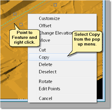
Once the Feature is copied to the clipboard, go to the window into which you wish to paste the Feature and click on this window to make it active. From the Main Menu select Edit/Paste. The Feature will be pasted into the Window.