|
<< Click to Display Table of Contents >> Blast Wizard |
  
|
|
<< Click to Display Table of Contents >> Blast Wizard |
  
|
The Blast Wizard functionality generates blast profiles for a pit or subsections of a pit. Most types of blast profiles can be modelled, and the system accounts for the volumetric effects of both blast swell and blast gain.
The Blast Wizard creates a three-dimensional blast profile using a two-dimensional extrapolated approach. For the purpose of generating the blast profile the strip is divided into evenly placed stations (Referred to as Blast Profile Stations). Station lines run perpendicular to the axis of the pit at any point, and the spacing of the stations is set by the user. The user defined blast profile is applied at each of the stations. This profile is adjusted to ensure the correct blast swell factor at each station. Volumes are calculated on a three-dimensional basis.
The Blast Wizard requires a number of design elements and requires the user to specify a number of parameters. The required design elements are:
•Pit Shell. This is a surface which defines the limits of excavation for the Strip. This surface does not need to include a low wall profile, however if it does this will improve the accuracy of the blast gain volume estimate.
•Blast Design Toe and Blast Direction. The Blast Design Toe is a linear feature which runs along the length of the blast. This feature line is used to orient the stations used to produce the profile, and hence it must run parallel to the pit axis. If the pit axis includes corners or other changes of orientation these must be incorporated in this Blast Design Toe. As well as orienting the blast, the blast toe determines the linear extents of the Blast Profile and is a line of demarcation for the lateral (cross – pit) extents of the in situ material to be blasted. The Blast Profile generated by the Blast Wizard will only extend to the ends of this Blast Design Toe. All in situ material to be blasted must be located down dip of the Blast Design Toe (i.e. the Surface Feature used as the Blast Design Toe must be located up-dip of the in situ material to be blasted). Typically the low wall toe from the Pit Shell is suitable for this purpose, in some instances it may need to be extended slightly at the ends. The Blast Direction defines the direction of blast movement relative to the Blast Design Toe. The figures below illustrate the Blast Design Toe:
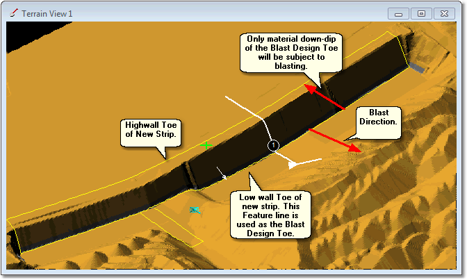
Blast Design Toe.
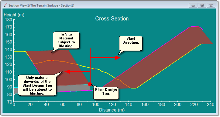
Blast Design Toe, Cross Section View.

Key Information
Note that only material located down dip of the Blast Design Toe will be used by the Blast Wizard to represent in situ blasted material. However, the post-blast profile will extend across this line and up-dip as far as necessary to conform to the design profile. Selecting an appropriately located Surface Feature for the Blast Design Toe is critical to achieving a valid result.
•Typical Blast Profile. This is a two-dimensional profile, drawn in a section window, which defines the typical shape of the blast in cross-section.
•Typical Low wall Profile. This is required in order to establish that component of the blast of material, which is cast to final spoil, and hence determine the Blast Gain. A Low wall Profile can be estimated using a low wall toe and parameters, or it can be a full spoil model which is part of the Pit Shell.
•Blast Swell. This is the swell factor by which material swells in going from bank in situ to blast. See notes below on Blast Gain and Swell Factors.
Many blast profiles swell the overburden and many cast some overburden to final spoil. Both of these characteristics influence the post blast swell factor. The Blast Wizard incorporates functionality to determine Blast Gain volume and blast to final swell factor. This information can optionally be copied automatically to Material Logs during the process of establishing the Blast Profile.
When the setup is complete, 3d-DigPlus applies the Typical Blast Profile at each station along the length of the blast. At each station, the volume in-situ is calculated for the in situ area covered by the span of the Station. The Typical Blast Profile is applied to the Station and is moved up and down as required to match the in-situ volume with blast swell applied. Additionally the blast gain can also be calculated and incorporated in the volume calculation. In this manner volumes are preserved locally and a surface is generated consistent with the user defined Typical Blast Profile. A texture can optionally be applied to the blast surface.
Blast Gain and Swell Factors.
The process of blasting will typically create a blast profile that both swells the original material and transports some to final spoil (Blast Gain). It is critically important with any 3d-DigPlus project that the correct spoil volume be produced.
The figure below illustrates in situ and total spoil volume components:
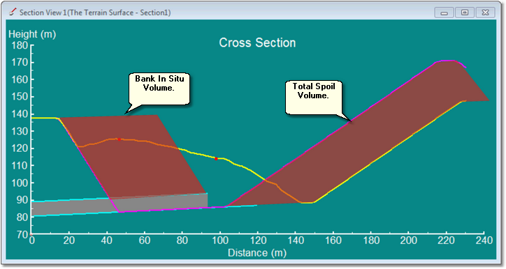
Bank In Situ Volume and Total Spoil Volume.
The relationship between bank in situ volume, spoil volume and Bank to Final Swell Factor is as follows:
(1) spoil volume = (bank in situ volume) * ( Bank to Final Swell factor)
The concepts of Blast Swell and Blast Gain complicate the calculation of spoil volume using equation (1) above. The Blast Gain effectively transports material to final spoil. If the correct spoil volume is to be achieved this cast material must be subject to the Bank to Final Swell Factor. The figure below illustrates Blast Swell and Blast Gain:
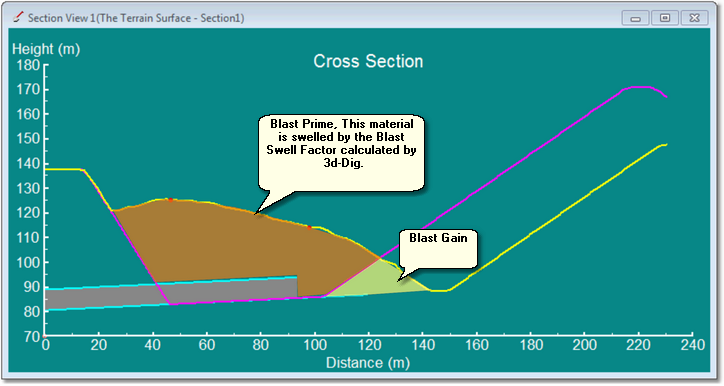
Blast Prime and Blast Gained Volumes.
The principles adopted by 3d-DigPlus to allow for the various swells occurring from blast to spoil are based on the principle that equation (1) above must hold true, that is the final spoil volume must equal Bank in situ volume multiplied by Bank to Final Swell Factor. The Blast Gain material is transported by the blast to its resting position within the final spoil pile; it is assumed therefore that this material is swelled fully in accordance with the total swell factor. The balance of the blasted material (Blast Prime) is subject to swelling during the blasting process by an amount referred to as the Bank to Blast Swell Factor. This material must be transported to final spoil and during this process subject to additional swell referred to as the Blast to Final Swell. These relationships can be expressed as follows (absolute volumes):
(2) (Blast Prime)*( Blast to Final Swell) + ( Blast Gain ) = ( Total Spoil Volume)
The user specifies the Target Average Blast Swell Factor, and draws the Blast Profile. This blast swell is referred to as "average" because the blasted material consists of two components: the Blast Gain component and the Blast Prime component. As the Blast Gain is fully swelled, and the Blast Prime is typically at a lesser swell factor, the swell under the Blast Profile is non-homogeneous. However, 3d-DigPlus must have a single swell factor to establish the Blast Profile at each station. It is not until the profile is produced, using the Target Average Blast Swell Factor, that the Blast Gain volume can be determined and the actual blast prime swell subsequently determined by back calculation. This explains the need for the initial Target Average Blast Swell Factor.
Typically the user will have an estimate of the expected swell within the Blast Prime region. This swell is referred to in 3d-DigPlus as the Bank to Blast Swell Factor and must be determined by 3d-DigPlus via a calculation once the Blast Profile is generated. For most typical cast blasts, the calculated Bank to Blast Swell Factor will be a little less than the Target Average Blast Swell Factor.

Tip
When modelling Cast Blasts the Target Average Blast Swell Factor should be set to a number a little higher than the expected in-the-field "blast swell". In most situations 1~2% will suffice and result in the calculated Bank to Blast Swell Factor which is close to the field number. The greater the Blast Gain component the greater this adjustment will need to be.
The Blast Wizard calculates the Blast Gain and the required Blast to Final Swell factor. These numbers can optionally be copied to Material Logs during execution of the Blast Wizard. In order to use this method the Material Logs need to be created before running the Blast Wizard, one Log to receive the Swell Factors, and one to receive the Blast Gain volume. The Log which receives the Swell Factors is used for subsequent simulation. The Log which receives the Blast Gain volume is used to record the material transported by the blast. It is strongly recommended that this option always be used for cast blasts. In this manner the correct Blast to Final Swell will be used, and reported Prime volume will be adjusted to account for the Blast Swell. The Material Log which receives the Blast Gain is required to maintain an audit trail of all material transported from in situ to spoil. These procedures are explained further in the following section.
In order for the above procedure to produce reliable results, it is important that the blast profile and the blast gain are reasonably consistent over the length of the blast. 3d-DigPlus calculates the total blast gain and averages this over every station used to create the Blast to Final Swell. If the profile and hence the gain are reasonably consistent,or the maximum Blast Gains are modest, this approach will produce reliable results.
However if the blast profile and gain change radically over the length of the blast, and the Blast Gain is a large proportion of the volume, the results will be less reliable. This depends on the magnitude and nature of the variation. In cases where the blast profile does change radically, it will generally mean that the nature of the pit and the mining methods will also vary widely. It is recommended in such cases that two independent blasts be conducted with separate Material Logs created for each blast. The subsequent simulation or manual excavation will need to change logs when excavation moves from the region of one blast model to the next.
 Key Information
Due to the complicating effects of blast gain the Blast to Final Swell Factor that appears in the Material Log will be different from the Target Average Blast Swell Factor specified by the user within the Blast Wizard interface.
The figure below shows a 3d-DigPlus file containing a strip ready for application of the Blast Wizard:
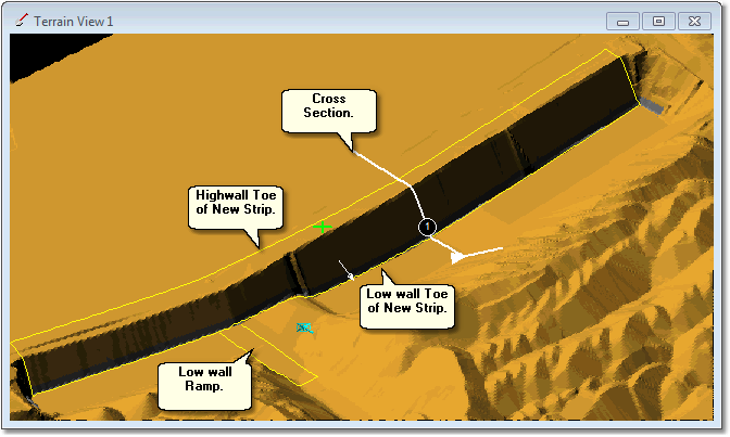
Strip with Elements Ready for a Application of Blast Wizard.
The 3d-DigPlus file will contain a surface for the Pit Shell and a surface for the Coal Roof. This file also contains a Surface Feature, which includes the highwall toe as shown in the figure above.
As the Blast Profile is drawn in a Section Window a suitable Cross Section must be present. This Cross Section must have the following characteristics:
•Its orientation must be perpendicular to the pit axis.
•It must extend on the highwall side at least as far as the high wall crest for the new Strip.
•It must extend on the low wall side as far as the blast profile is required to extend.
If a suitable Cross Section is not present, the Blast Wizard will issue an error message at the appropriate time.
When all the necessary elements are assembled in the 3d-DigPlus file the Blast Wizard can be started by using the Main Menu option Terrain/Blast Wizard. This will produce the Blast Wizard dialog.
Blast Wizard Dialog, Select Feature page.
The first page of the Blast Wizard Dialog is the Select Feature page:
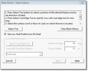
Blast Wizard Dialog, Select Feature Page.
The Select Feature page of the Blast Wizard Dialog contains the following components:
Select Toe button.
The first task in creating a blast profile is to identify the Blast Design Toe. In most situations the low wall toe (New Strip) will be used for this purpose. The following description shows how a part of this low wall toe is selected as the Blast Design Toe
When the Select Toe button is clicked, the Blast Wizard dialog is temporarily dismissed and the Terrain Window becomes active. The Terrain Cursor is moved and placed on top of the appropriate Toe, a left click results in the Cursor snapping to the Toe. The cursor will now respond to sideways mouse movement. Moving to the left causes the cursor to track clockwise around a feature, moving to the right causes the cursor to track counter-clockwise. The cursor is moved to one end of the Blast Design Toe and a left click is performed. As the mouse is subsequently moved a portion of the toe becomes highlighted. The Cursor is moved to the other end of the desired Blast Design Toe at which point the length of the required length of toe will be highlighted. A left click will confirm this section of toe is to be used as the Blast Design Toe.
At this point the Terrain Cursor will be released from the feature but remains in select mode. In this mode, as the cursor it is moved to either side of the selected Toe, direction arrows will appear. These direction arrows indicate the direction of cast for the proposed Blast Profile. The cursor is moved so the direction arrows point in the appropriate direction (up dip, towards the low wall,). At this point a final left click will complete this process, and focus will return to the Blast Wizard Dialog. The following video clip illustrates this procedure:
Clear Blast History Button.
In some instances two Blast Profiles may overlap. An initial Blast Profile is generated and a subsequent Blast Profile must be generated which merges with the first. In such cases it is important that the portion of the original Blast Profile, in the region of overlap, is not modified when the second Blast Profile is generated. To avoid this each time a Blast Profile is generated 3d-DigPlus retains a history of the part of the topography which has been subject to the Blast Profile. This portion of Topography which is marked as blasted will not be modified by subsequent applications of the Blast Wizard. The Clear Blast History button will remove this record of blast history. This may be important for modelling of multi-pass operations, so that the same portion of terrain can be correctly blasted in a subsequent pass. In most situations however, blast overlap will not occur and the user does not need to be concerned with the Blast History.
Get Low Wall Profile from Pit Shell Checkbox.
When a cast blast is modelled some material will be cast and placed within the final spoil profile. This material is referred to as Blast Gain and in order to accurately determine the appropriate post blast swell factor this Blast Gain volume must be determined. Determining the Blast Gain volume requires a model of the low wall profile. The Blast Wizard provides two means of modelling the low wall profile:
1.Estimate based on low wall toe and profile parameters.
2.Direct calculation using a surface model of the low wall profile.
Method 1 requires a low wall toe feature and various parameters; method 2 requires that a surface be present which models the low wall profile.
The Get Low Wall Profile from Pit Shell checkbox controls which of these two methods is used to model a low wall. When this checkbox is selected method 2 is used. The Pit Shell surface is selected on the following page of the Blast Wizard dialog.
Low Wall Parameters group.
This Group controls the parameters used when Method 1 is used to estimate the low wall profile. The low wall profile is estimated using the following elements and parameters:
•Low wall coal edge toe. This is a Surface Feature running along the toe of coal on the low wall side. The appropriate Feature is selected by clicking the Select Coal Edge button.
•Undercut Angle. This is the angle of the lower portion of the low wall profile. This may be repose angle or some other undercut angle. The Undercut Angle is specified as a parameter input into the Undercut Angle field.
•Trench Width. Where the low wall incorporates a trench along the coal edge the width of the trench is specified via the Trench Width parameter. The Trench Width is specified as parameter entered into the Trench Width field.
•Low Wall Toe Bind Surface. This is the Surface on which the low wall coal edge toe is located. It is typically the floor of coal. The Low Wall Toe Bind Surface is selected using the Low Wall Toe Bind Surface pulldown list.
The user must identify the low wall coal edge. To do this the Select Low Wall Coal Edge button is clicked. The Blast Wizard dialog is temporarily dismissed and the Terrain Window becomes active. The user selects the relevant toe or if necessary a subsection of this toe. The following video clip demonstrates this procedure:
Once the low wall coal edge toe is selected, and the other parameters input the estimated profile is created by 3d-DigPlus using the following procedure:
•The low wall coal edge toe is draped onto the bind surface (typically coal floor).
•The draped low wall coal edge toe feature is copied up dip by the Trench Width distance, forming the trench edge feature.
•The trench edge feature is projected vertically a substantial distance at an angle equal to be undercut angle forming the spoil crest feature.
Using the three features described above, low wall coal edge toe, trench edge and spoil crest a temporary surface is created which approximates the strips low wall profile.
The following figure shows a cross-section through a blast illustrating the above points:
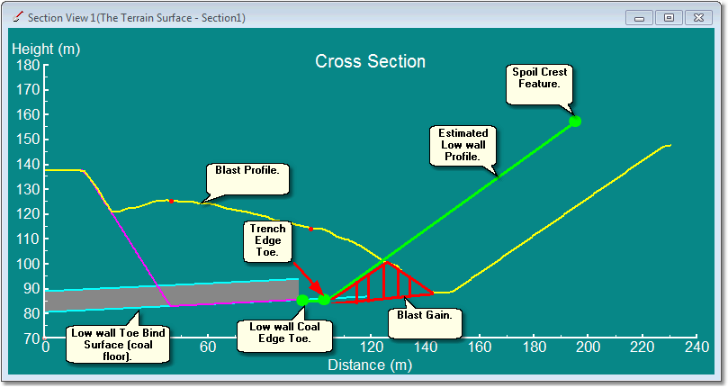
Blast Gain Region, Established by Estimated Low wall Profile.
The following figure shows the situation where a Surface with low wall profile is used to determine the region of Blast Gain:
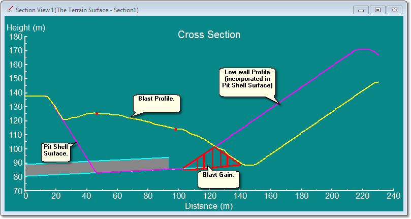
Blast Gain Region, Established Using a Surface with Low wall Profile.
Both of these methods can produce adequate estimates of Blast Gain and subsequent swell factors. The main difference lies in the fact that the estimated blast profile does not account for ramp voids. The estimated method will assume that the low wall profile continues through the ramp and material deposited by the blast within this profile is located in final spoil. Material blasted into ramp voids must be transported to adjacent spoil. Hence using the low wall estimate method increases slightly the estimate of Blast Gain. This has the effect of slightly over estimating the Blast to Final spoil factor. Therefore this approach is conservative in that it over estimates the volume of the final spoil. In most situations this overestimate should be quite modest.

Key Information
As described above the approximate method for modelling the low wall profile will typically over estimate the Blast Gain volume slightly. As a result when all excavation modelling for the strip is complete an audit of all volumes associated with the strip (prime material excavated in stripping process + Blast Gain volume) will typically produce Prime volume slightly greater than the original prime in-situ.
Next Button.
Once the Blast Design Toe is selected, and the appropriate elements and parameters input for the low wall estimation, the next Button at the bottom of the dialog is clicked.
Blast Wizard Dialog, Set Parameters page.
The Blast Wizard Dialog Set Parameters page is shown in the figure below:
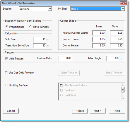
Blast Wizard Dialog, Set Parameters Page.
The Set Parameters page of the Blast Wizard Dialog contains the following components:
Section Pulldown List.
The standard blast profile is input by drawing the desired profile in a cross-section window. A cross-section must be present within the area of the blast and oriented approximately at right angles to the axis of the pit. There may be potentially several cross-sections in this area, the desired cross-sections selected using the Section Pulldown list. Note that cross-sections are numbered in the terrain window and these are numbers that appear in the Section Pulldown list.
Section Window Height Scaling group.
3d-DigPlus has two methods of fitting surfaces in a cross section window:
•Proportional.
•Fit to Window.
The Proportional method uses the same scale on the vertical and horizontal axes, so there is no vertical exaggeration. As the process of drawing the design blast profile is a visual one it is generally best to use the proportional method and this is the default method.
The Fit to Window method stretches the data vertically to fit the cross section window.
Pit Shell Pulldown List.
The Pit Shell surface is required to delineate the material in the strip to be blasted. The appropriate surface is selected using the Pit Shell pulldown list. If the Get Low Wall Profile from Pit Shell checkbox was selected, on the first page of the Blast Wizard dialog, the low wall in the Pit Shell surface will be used to determine the Blast Gain.
Calculation Group.
The fields in this group control the spacing of the Stations used to create the blast profile over the length of the strip. These stations are explained in the section above Blast Wizard Principles of Operation. The default setting is 15 m and this is generally adequate for most purposes. The Calculation group also contains a Transition Zone Size parameter. The Blast Wizard creates a transition between adjacent stations and this parameter controls how this transition is applied. The default value of 15 m is generally adequate for most purposes.
Corner Shape Group.
The typical blast profile as input by the user applies to a straight, or approximately straight, section of the strip. If the strip incorporates a distinct corner the form of the blast must vary in the region of the corner. The Blast Wizard recognises two types of corners:
•Inside Corner. This is a corner where the highwall of the strip is on the convex side of the corner, and the blast throw is towards the concave side of the corner. At an inside Corner the blasted material has less room to be accommodated on the low wall side and the blast generally heaves more and casts less.
•Outside Corner. This is a corner where the high wall of the strip is on the concave side of the corner, and the blast throw is towards the convex side. At an outside Corner the blasted material has more room to be accommodated on the low wall side and the blast generally heaves less and casts more.
Corner Shape parameters control the way in which the form of the blast is modified to accommodate the restrictions of the corner geometry. The default parameters produce adequate results in most situations. If the resultant shape of the corner is not acceptable the blast can be removed using the Undo button, and the Blast Wizard reapplied with different corner parameters. Keep in mind that regardless of the form at the corner the Blast Wizard will be dealing with the volumes appropriately.
Texture Group.
The Blast Wizard can optionally add texture to the blasted material. Adding texture clarifies that the area has been subject to blasting and this is the default setting. The Texture Ratio and Max Height parameters control the nature of the texture applied.
 Tip
Tip
Adding texture creates a clear visual cue that a section of the topography has been subject to blasting. When modelling casts blasts, where the blasting swells the in-situ material, subsequent excavation must use the appropriate material log set with the appropriate Blast to Final Swell Factor. The use of blast texture assists this process by making it clear to users when they are excavating blasted material. Therefore use of the default Texture settings is strongly recommended.
Use Cut Only Polygon Group.
The Blast Wizard is usually applied to model cast blasts. These are blast where the material is subject to at least a moderate amount of movement across the pit and the blast profile often exhibits significant vertical slump in the region of the in-situ pre-blast topography. The blast effectively removes material from the highwall side and deposits it in the adjacent void. In the case of cast blasts there is normally no ambiguity about the regions of blast removal and deposition. However some blast types, particularly stand-up blasts, may result in some ambiguity. Cut Only Polygons are used to remove this ambiguity and their use is explained in the following section: Stand-up Blasts and the use of Cut Only Polygons. Cut Only Polygons are not required for the majority of blast types.
Limit by Surface Group.
In order to model the blast correctly the Blast Wizard must have enough information to accurately determine the volume of blasted material at each station. For this a Pit Shell surface must be present. However the Pit Shell will typically extend to the floor of coal. Therefore if the Pit Shell alone is used the Blast Wizard will treat all material within the Pit Shell as being subject to blasting, including the coal. In order to prevent this, the coal roof surface must be nominated as a Limit Surface. Doing this will ensure that the Blast Wizard uses all material within the Pit Shell but limits this to the level of the coal roof surface. If other surfaces also limit the blast these too can be incorporated.
The Limit by Surface Group includes a checkbox labelled Limit by Surface. When this checkbox is selected the adjacent Surface list is enabled. Each Surface in the list has a checkbox. When the checkbox for a particular Surface is selected this surface will be used as a Limit Surface. Typically only the roof of coal Surface needs to be included in this list.
Next Button.
When the Set Parameters page is complete the Next Button is selected.
Blast Wizard Dialog, Draw Profile page.
The Blast Wizard Draw Profile page is shown in the figure below:
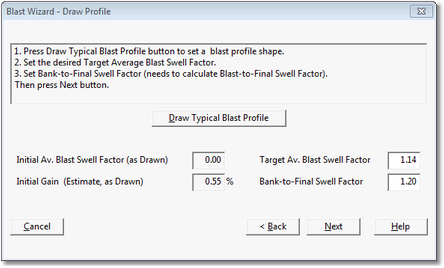
Blast Wizard Dialog, Draw Profile Page.
The Draw Profile page requires a number of parameters to be input and then allows the typical Blast Profile to be drawn in the cross section window. The Draw Profile page has the following components:
Target Average Blast Swell Factor.
This field is enabled for user input, and the design Blast Swell Factor is input into this field. This is the swell factor applied when the Blast Wizard produces the Blast Profile surface. At each station used for modelling the blast profile the user-defined profile will be adjusted vertically to achieve this design swell factor (see previous topic: Blast Gain and Swell Factors).
Initial Average Blast Swell Factor field.
When the user draws the blast profile in this section window the Blast Wizard calculates the Blast Swell Factor produced by this profile, in its location as drawn, and reports it in the Initial Average Blast Swell Factor field. Drawing a suitable blast profile is typically an iterative process and several profiles are often drawn before a suitable one is produced.
 Key Information
The Blast Wizard will always adjust the Typical Blast Profile vertically, at each station, to achieve the specified Target Average Blast Swell Factor. This occurs regardless of how much difference exists between the Target Swell Factor and the Initial Swell Factor (implied by the as-drawn profile). However if a large difference exists between the two swell factors the profile as applied at each station may appear different from what the user expects. It is therefore best to redraw the blast profile as required in order to achieve an Initial Blast Swell Factor which is close to the Target Blast Swell Factor.
Bank to Final Swell Factor.
This is the user specified total swell factor. The volume of the final spoil pile must equal the bank in-situ volume times the Bank to Final Swell Factor. The Blast Wizard uses the Bank to Final Swell Factor plus the Blast Gain volume to establish the Blast to Final Swell Factor. The Blast to Final Swell Factor ensures that blasted material, subsequently excavated and dumped, will have the correct swell to produce a spoil pile of the correct swelled volume. The following formula describes this relationship:
Bank in-situ volume * total swell factor = Blast Gain volume(fully swelled) + Blast Prime(blast swelled) * Blast to Final Swell Factor.
Fully swelled means swelled by the Bank to Final Swell Factor. Blast Prime refers to the portion of the blast volume which is not cast to final spoil ( i.e. that material which must still be excavated and dumped to final spoil).
Initial Gain.
Once the user draws a Blast Profile the Blast Wizard estimates the Blast Gain for this profile. This number is reported in the Initial Gain field. This is referred to as an estimate as it is the gain at that point in the strip where the Typical Blast Profile is drawn. Blast Gain at other points in the strip may vary from this estimate.
Draw Typical Blast Profile Button.
When all the appropriate parameters are input the user can click the Draw Typical Blast Profile Button. This will open up the section window in which the profile is drawn. A blast profile is drawn to mimic the expected profile and blast swell factor. If the reported Initial Average Blast Swell Factor is significantly different to the specified Blast Swell Factor it is generally best to redraw the section until a reasonably close match is achieved. The Draw Typical Blast Profile Button can be used as many times as required to redraw the Blast Profile. Each time the Blast Profile is redrawn the Blast Wizard will display the previous profile in this section window to assist in drawing the modified profile.
If the reported Initial Average Blast Swell Factor is significantly different to the specified Blast Swell Factor, and the user proceeds with this profile, the Blast Wizard will adjust the vertical location of the profile at each station to achieve the exact specified Blast Swell Factor. However the actual vertical location of the profile at each section may differ somewhat from what the user expects in such cases.
The following video clip illustrates the drawing of a Typical Blast Profile:
Next Button.
Once all parameters are input and a suitable Typical Blast Profile is input the next button can be selected which opens the final Blast Wizard Dialog page.
Blast Wizard Dialog, Blast Volumes page.
The final page of the Blast Wizard dialog is the Blast Volumes page which is shown in the figure below:
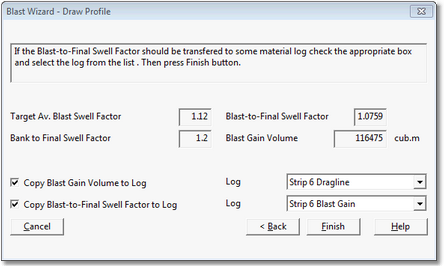
Blast Wizard Dialog, Blast Volumes Page.
This page of the Blast Wizard allows two Material Logs, nominated by the user, to be modified in accordance with the blast. One log is modified to incorporate the Blast to Final Swell Factor, and the other log has the Blast Gain volume added to it. These Material Logs must be established by the user in advance of running the Blast Wizard.
In order for any modelling work conducted in 3d-DigPlus to be valid the overall swell factor which applies to prime in-situ (referred to in 3d-DigPlus as Bank to Final Swell Factor) must apply between prime in-situ and final spoil. When material is excavated and dumped without any blast modelling a single swell factor, the Bank to Final Swell Factor, can be used effectively. However the process of creating a blast profile can alter this simple relationship as a result of a combination of blast swell and blast gain. These factors are discussed earlier in this topic. If a particular blast has Blast Swell applied and/or a significant volume of Blast Gain the simple Bank to Final Swell Factor will not apply. The Blast Wizard allows for this by optionally modifying two selected Material Logs. One of these logs (empty) will have the following swell factors incorporated:
•Blast Swell Factor (i.e. Bank to Blast Swell Factor)
•Blast to Final Swell Factor
The other log will also incorporate these swell factors and in addition will have the Blast Gain volume added to it (cut and fill equal to blast gain volume).
The Blast Swell Factor is the swell factor which must be applied to unblasted (bank) Blast Prime material to produce blast swelled material. It is also the swell factor by which a given volume of (post-blast) Blast Prime material must be divided to produce the original prime in situ volume for reporting. The Blast to Final Swell Factor is the swell factor which must be applied to any material within the blast profile which is excavated and dumped. This will result in a final spoil pile of the correct volume. When the material from the blast profile is excavated its volume is modified using the Blast Swell Factor to produce an accurate prime volume.

Key Information
Some subsequent excavation processes, such as dragline and bulldozer, will excavate material and dump it temporarily to a bench before re-excavating to final spoil. Material which is excavated two or more times is referred to as rehandle. 3d-DigPlus recognises rehandle and does not re-swell such material. Any rehandle volume reported will have the appropriate swell factors applied and the correct volume will be reported as a bank volume. The material will also be reported as a swelled volume, however no additional swell is added at the time that the rehandle material is excavated.

Warning!
In a 3d-DigPlus file where no blasting simulation is used, a single swell factor can be applied universally (i.e. applied to all excavations). However, when a blast profile is created, the Blast Swell means that the blasted material must be subject to its own unique Blast to Final Swell Factor in subsequent excavation. The user must ensure a Material Log is set up with the appropriate Blast to Final Swell Factor, and that this Material Log is always used with any process which excavates blasted material. If a 3d-DigPlus design file has a variety of blasted and non-blasted material, each with its own Swell Factor, Material Logs must be set up as necessary for each material type, and the user must ensure that the correct logs are used at the correct time. The exception to this rule is a simple stand-up blast where the Blast Swell is 1.0. In such cases Blast to Final Swell Factor will remain the same as the general Swell Factor.
The Blast Volumes Page has the following components:
Target Average Blast Swell Factor. This is the user specified blast swell factor. This swell factor will be applied to the blast prime material within the blast profile.
Blast to Final Swell Factor. This is the swell factor, calculated by the Blast Wizard, which must be applied to blast prime material when it is subsequently excavated. This results in material which is fully swelled.
Bank to Final Swell Factor. This is the user specified total swell factor. This is the swell factor by which bank in-situ material must be swell to produce the correct volume in the final spoil.
Blast Gain Volume. This is the actual Blast Gain volume for the complete blast. Depending on the method used to model the low wall profile, it is subject to the limitations described above.
Copy Blast Gain Volume to Log Checkbox. When this checkbox is selected calculated Blast Gain volume will be copied to a Material Log. The adjacent Log pulldown list allows the receiving Log to be selected from a list of existing Material Logs.
Copy Blast to Final Swell Factor to Log Checkbox. When this checkbox is selected the Blast Swell Factor, and the Blast to Final Swell Factor are both copied to the nominated Material Log. The adjacent log pulldown list allows the receiving Log to be selected from a list of existing Material Logs.
Finish Button. When the set up is fully complete the Finish button is selected and the blast profile is created. The figure below illustrates a typical blast profile:
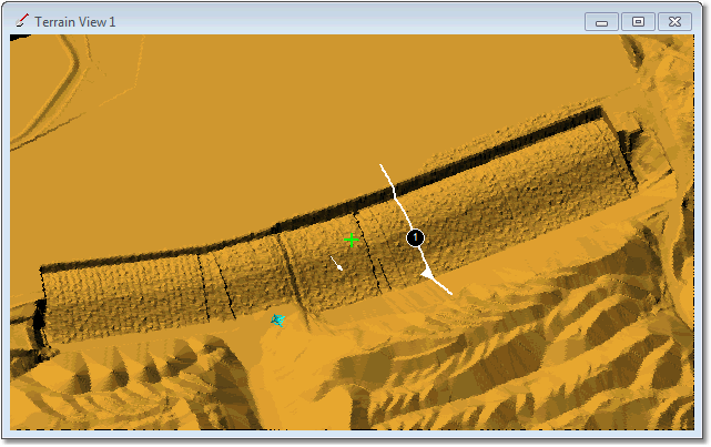
Typical Blast Profile.
The Blast Wizard is usually applied to model cast blasts. These are blast when a material is subject to at least a moderate amount of movement across the pit and vertical slump. In such cases all material deposited by the blast is below the level of the in-situ blasted material. The following figure illustrates this:
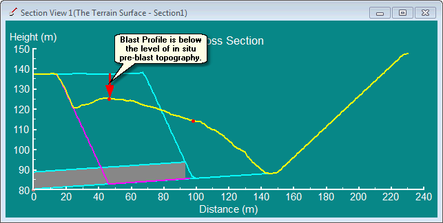
Typical Cast Blast Profile.
The Blast Wizard can also be used to model stand-up blasts. These are blast profiles where the blasted material is subject to only modest horizontal movement. The figure below illustrates a stand up blast:
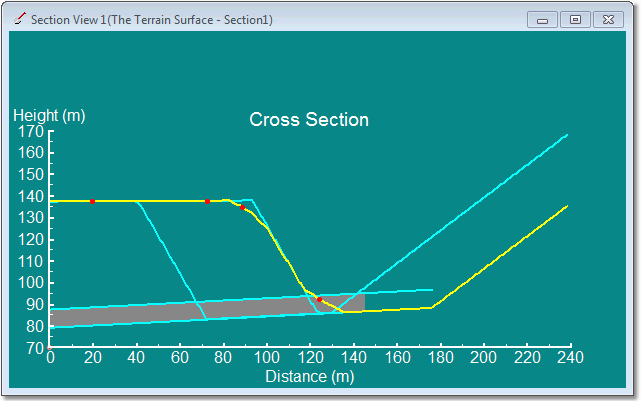
Typical Stand-up Blast Profile.
The blast illustrated above results in a modest amount of material thrown from the crest of the existing highwall and deposited at the toe.
As described in the introduction to this topic, the Blast Wizard does not model the mechanics of the blasting process but instead takes a typical blast profile and applies it in a consistent manner across the length of the strip. This process effectively "cuts" material from the region of in-situ pre-blast material and deposits it in the adjacent void. In the case of the cast blast type described above, there is no ambiguity between the regions where material is cut and deposited. This is due to the fact that the blast profile, in the region of in-situ pre-blast material, is at all points below the level of the pre-blast topography.
However in the case of the stand up blast shown above there is a possibility of the typical blast profile being placed above the pre-blast in-situ topography at some stations .If the typical stand-up blast profile is drawn at a deep section of the strip, when it is applied at a less deep section the profile may imply material being deposited on the highwall side:
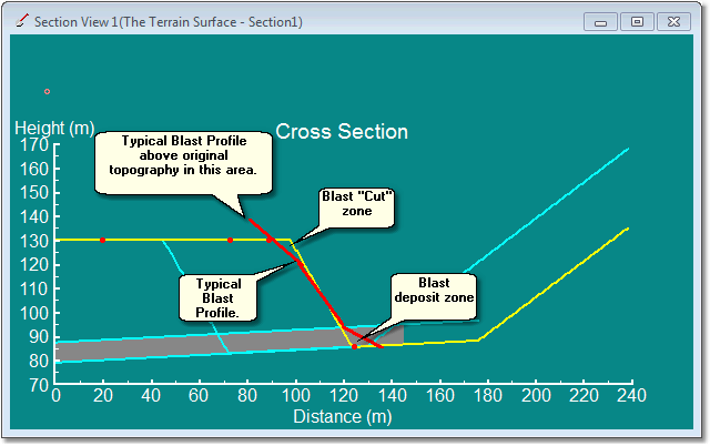
Typical Stand up Blast Profile, Applied at Shallow Section of Strip.
In the above example the Typical Blast Profile is above the level of the pre-blast in-situ topography. If this situation is left unchecked the Blast Wizard has no way of knowing that material will not be deposited by the blast in this area. Indeed some blast profiles may be designed to create heave in this area and will require material to be deposited here.
The Cut Only Polygon is a method used to inform the blast Wizard that no blasted material should be deposited within a given area. The user selects or draws a closed polygon and the blast Wizard will not deposit material within the bounds of this polygon.