|
<< Click to Display Table of Contents >> Setting up the Excavation Templates |
  
|
|
<< Click to Display Table of Contents >> Setting up the Excavation Templates |
  
|
Setting up the Excavation Templates
You should be familiar with the processes of Establishing Pit and Block Lines and Staged Excavations.
Prior to setting up the Stage Excavation for the Automated Dragline Simulation you will need to have established a pit and Block Lines using a block alignment and spacing suitable for the dragline simulation. The first step in setting up the Excavation Template is to select the correct Pit, Pit Shell and Strip Number:

Excavation Template – Basic Settings for Automated Dragline Simulation.
Note that in the above description and figure a single Strip number is specified. An Automated Dragline Simulation can span several strips, see topic Dragline Simulation Spanning Pits.
The Automated Dragline Simulation uses the Staged Excavation type. Having established the basic Excavation Template the Staging parameters must be set up on the Staging page of the Excavation Settings dialog:
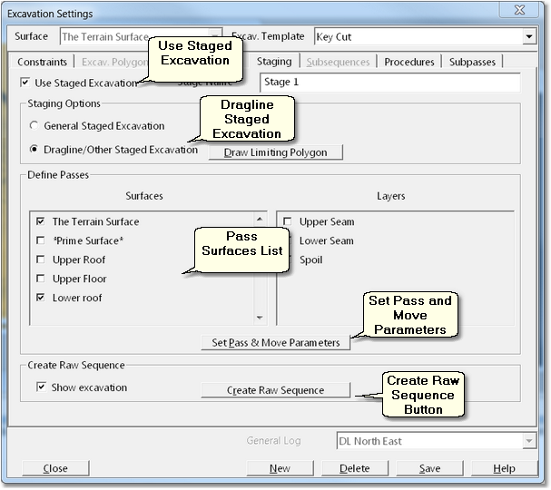
Excavation Settings Dialog – Staging Page.
Clicking the Use Staged Excavation checkbox will set the Template as a staged excavation and enable the settings on the Staging page.
In the Surfaces list the surface representing the floor of pass is selected. Frequently this is the only surface which requires selection. However for complex operations one or more intermediate surfaces may be required to subdivide the pass for the purpose of creating Moves.
Having set up the basic Staging parameters the next step is to create the Moves. Clicking on the Set Pass and Move Parameters button will open up the Passes & Moves dialog:
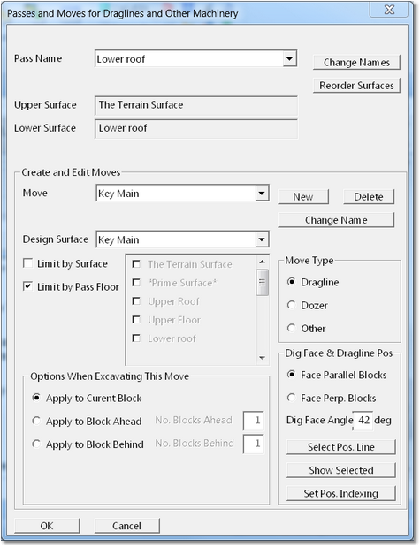
Pass and Moves Parameters Dialog.
Note that the full name of this dialog is "Passes and Moves for Draglines and Other Machinery. Although primarily intended for dragline simulation, this suite of functionality can apply moves which excavate and dump and simulate a variety of equipment types including Bulldozers.
The parameters that appear and are set in this dialog apply to the current Pass as defined in the previous dialog. This Pass is named after the pass floor surface in the above example this is the Lower Roof surface (roof of lower seam).
The first step is to create a new Move, clicking the New (Move) button will open up the New Move dialog:
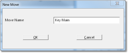
New Move dialog.
The desired name for the new Move is keyed in to create the Move.
Once the Move is created its parameters can be set up in the Pass and Moves Parameters dialog. The parameters are as follows:
Design Surface. The Design Surface is the surface which limits the extent of the Move excavation. It is created in advance using the Dragline Surface tool.
Limit by Surface checkbox and Surface List. Selecting the Limit by Surface checkbox will enable the adjacent Surfaces list. The Surfaces List shows all surfaces in the 3d-Dig file and any surface can be selected as a Limit Surface. Any surfaces selected will be used to clip the Moves excavation.
Move Type group. This group allows the type of Moved to be selected the options are Dragline, Dozer and Other.
Move Excavating Options group. The options in this group control the way the Move is excavated as part of a Procedure. The Procedure excavates a Sub Pass as a series of contiguous blocks, excavating the current block then the following block and so on. In some operations all moves in the Procedure will be performed on the current block. For example a simple key bridge operation will perform all moves to complete the current block before moving to the following block. However some more complex procedures will need to excavate some material in advance from the following block, and possibly in some cases some remnant material from the previous block. The Move Excavating Options allow a particular move to be located in either the current block, the block ahead or the block behind. Note that for very complex and unusual operations which may require excavation of several blocks in advance this will need to be modelled using a Sub-Pass.
Dig Face & Dragline Positioning group. The items in this group control the way the dragline and dig face are positioned, and the way the dragline is incrementally positioned while excavating the Move. The Dig Face & Dragline Positioning group has the following elements:
•Dig Face radio buttons. There are two options for locating the dig face (excavation batter immediately in front of dragline when excavating), Face Parallel to Blocks Face Perpendicular to Blocks. Face Parallel to Blocks produces a crest of Dig Face which is parallel to the blocks (typically perpendicular to the pit axis), a typical key bridge operation would utilise this setting. Face Perpendicular to Blocks produces a crest of Dig Face which is perpendicular to the blocks (typically parallel to the pit axis). A chopping operation conducted from a low wall bench would typically utilise this setting.
•Dig Face Angle. This is the excavated angle of the dig face, typically around 45°.
•Set Positioning Line Button. This button allows the user to select a Surface Feature which is used for dragline positioning. This Surface Feature may be created for the purpose by the user or it may be one of the strip design lines.
•Set Position Indexing button. This button allows the user to set parameters which control the dragline's position indexing (fine detail positioning and positioning relative to the Positioning Line). Clicking this button will open the Dragline Position Indexing dialog:
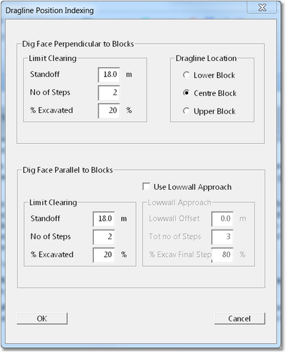
Dragline Position Indexing Dialog.
The various settings in this dialog are explained in the following topic Automated Dragline Simulation Example.
Once the settings on the Staging page are complete the broad detail of the excavation and of the Dragline Moves will have been defined. To complete this procedure the Create Raw Sequence button is clicked. At this stage the system will excavate The area within the Limit Polygon and create a Raw Sequence. The Raw Sequence is a list of all blocks within the user defined Limiting Polygon.
The following key points should be noted about the Dragline Automation Raw Sequence:
•The total span of Block Lines is that which exists within the user defined Limiting Polygon.
•If a particular Pass Surface does not exist at a particular Block Line, the Block will not be represented in the Raw Sequence.
The next step is to assemble the Moves into Procedures.This is done on the Procedures page of the Excavation Settings Dialog:
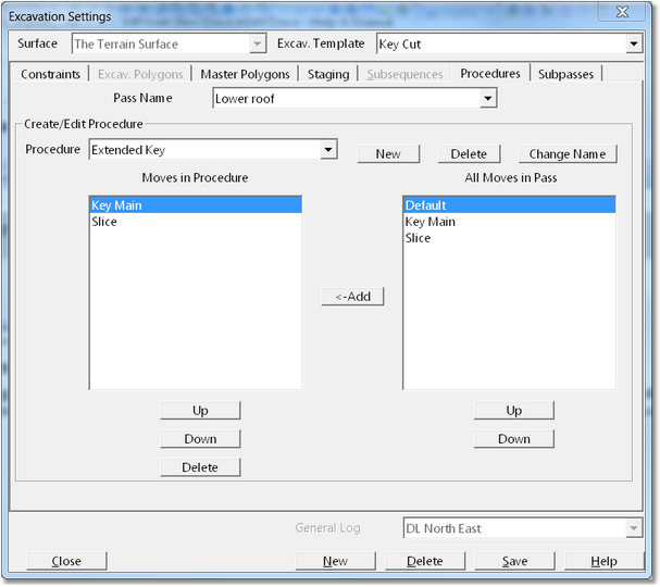
Excavation Settings Dialog – Procedures Page.
The Procedures page has the following elements:
Pass Name pulldown list. This pulldown list contains a list of all Passes in the current Excavation Template.
Procedure pulldown list and buttons. This Pulldown list contains a list of all Procedures in the current Pass (Pass selected in the Pass Name pulldown list.). When a particular Passes first selected there will be no Procedures available. A new Procedure is created by clicking the New button. An existing Procedure can be deleted with the Delete button. The name of a Procedure can be changed using the Change Name button.
Moves in Procedure list. This list shows all Moves in the currently selected Procedure in order of execution.
All Moves in Pass list. This list contains a list of all the Moves which have been created for the current Pass. These are moves created using the tools outlined above.
Add (moves) button. When the Add button is clicked the Move currently selected in the Moves in Pass list will be added to the procedure and appear in the Moves in Procedure list. The procedure is built by selecting the moves in order of extra tuition and clicking the add button to add them one at a time.
Procedure Editing Buttons. Below the Moves in Procedure list are three buttons labelled Up, Down and Delete. Individual Moves in the Procedure can be selected and manipulated in position or deleted using these buttons.
Once the necessary Procedures are complete the Sub Pass is assembled. The Sub Pass is assembled using the settings on the Sub Pass Page of the Excavation Settings Dialog:
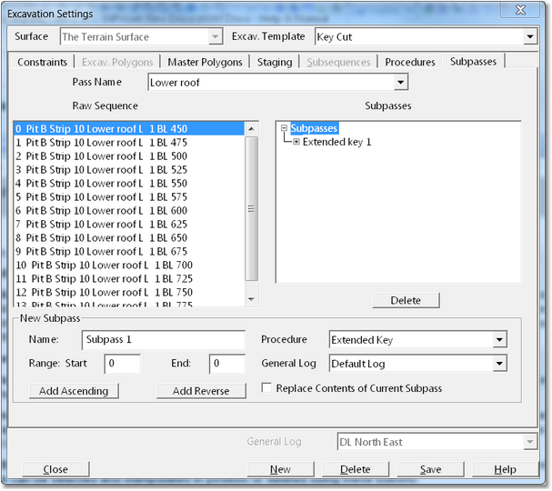
Excavation Settings Dialog – Sub Pass Page.
To create a new Sub Pass the following procedure is used:
•Using the Pass Name pulldown list select the Pass in which the proposed Sub Pass will operate. The Raw Sequence for this pass will then appear in the Raw Sequence list.
•Using the Procedure Pulldown list (bottom right of this dialog) select the procedure which will be utilised by the new Sub Pass.
•Using the General Log pulldown list (bottom right of this dialog) select the appropriate General clapped log to which volumes will report.
•In the Name field (under the Raw Sequence list) enter the name of the new Sub Pass.
•In the Raw Sequence list select the first block for the proposed Sub Pass, then using Shift Click select the ending block for the proposed Sub Pass. The Range Start field and End field will now showed the selected Block Range.
•Finally to create the Sub Pass, click either the Add Ascending or Add Reverse button to create the Sub Pass with the desired order of block execution (ascending or descending).
The newly created Sub pass will appear in the Sub passes list. Immediately to the left of the Sub pass name is a small button labelled "+", clicking this button will expand the Sub Pass showing all blocks included and their order:
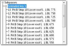
Excavation Settings dialog - Sub Pass Page – Expanded Sub Pass.