|
<< Click to Display Table of Contents >> Running a Truck Shovel Simulation |
  
|
|
<< Click to Display Table of Contents >> Running a Truck Shovel Simulation |
  
|
Once the Truck and Shovel simulation is set up using the procedures outlined in the previous topics, it is ready to be run. The following topic briefly outlines a few settings which influence the following:
•The appearance of the simulation in the active Terrain Window, and consequently the appearance of the captured animation.
•The information which is stored to the report file.
•The information which are stored to the Truck file.
Prior to running the Truck and Shovel Simulation the The active Terrain Window should be set up correctly and the General Capture Settings should be established. From the main menu select Options/Capture Settings.
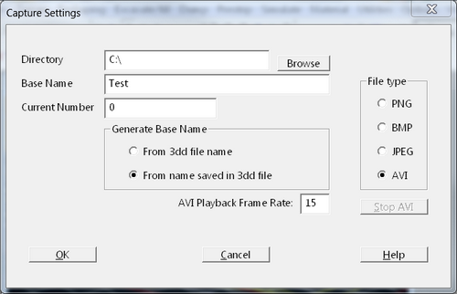
The capture file type, name and the folder in which the file or files are saved are controlled by the general (program wide) Capture Settings. From the Main Menu select Options/Capture Settings. This will open the Capture Settings dialog:

Capture Settings Dialog.
In the above figure the File type AVI has been selected. This will create a single video file which will play with the default video player on your computer. Using this file type makes it easy to pause and rewind and carefully check the Supersequence.
If the Supersequence you are checking is very large it is important to use optimal settings to minimise the run time. The following are recommended:
1/ Use the Window Appearance settings to switch off the display of the following in the Active Terrain Window:
•Surface Features
•Section Features
•Excavation Polygons
•Dump Line
•Dump Area
2/ Use the Fast Draw settings (Terrain/Fast Draw Settings) to select the Rarefied Grid option, select suitable Rarefied Grid settings to speed up the display of rendered windows.
Note that option 2 may not be necessary, implementing the recommendations in option 1 will usually be sufficient to produce a fast running Supersequence.
When the Supersequence is complete it is checked by running the video file captured for the Supersequence.
Truck and Shovel Simulation is generally have a large number of assigned Dumps. The Dump Parameters for each assigned Dump will critically influenced the speed of dumping and hence the speed of the Simulation.
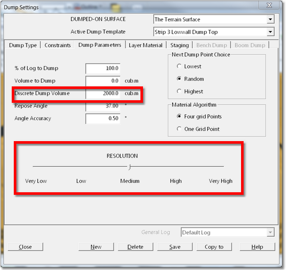
The settings in the Dump Parameters page of the Dump Settings dialog contain the setting Dump Resolution. The Dump Resolution, in conjunction with the Discrete Dump Volume, have a critical effect on the speed of dumping. Reducing the Dump Resolution will dramatically increase the speed of dumping.

Dump Resolution Setting.
The Dump Resolution has a major effect on the speed of Dumping Simulation, which is a major component of Simulation time. Reducing the Dump Resolution results in the system dumping material on a thinned version of the Terrain Grid. There is no loss in accuracy of reported Volumes however the dump is modelled at a lower resolution and this can result in a course appearance of the dump and less volume reporting to a given dump. Generally this volume reduction is small, but each case it should be assessed individually. When the Dump Resolution is reduced the Discrete Dump Volume should also be increased.
In the process of setting up a Simulation, doing a check Run of the Simulation and doing a Final run, all of the associated dumps will require different Dump Resolutions at different stages of the process. A low Dump Resolution will be used during the checking phase, and full resolution will generally be used for the final Simulation. The Dump Settings dialog has a Copy to button which allows the appropriate Resolution settings to be set in one Dump Template, and these settings then copied to a group of selected Templates. This makes the process of modifying the Dump Resolution settings across many templates quick and reliable. It is described in detail in the topic Copying Dump Parameters.
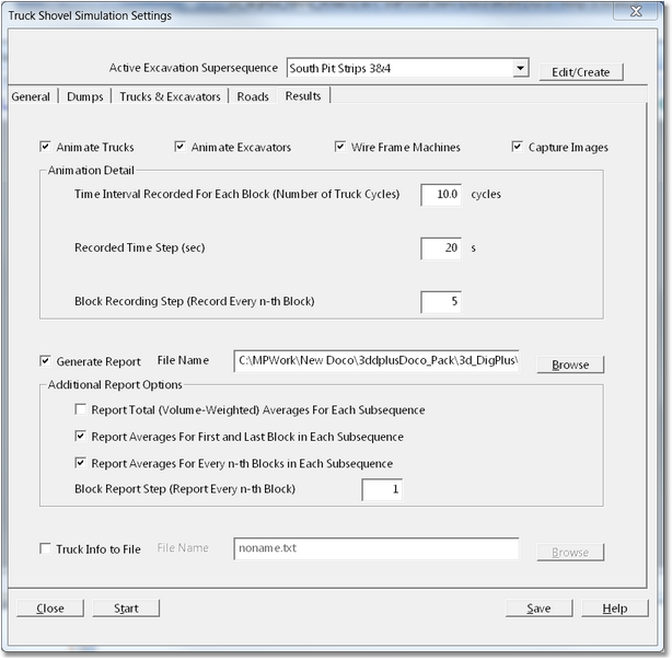
Most Stimulation Settings have been covered in the previous topics. This topic covers the runtime Simulation Settings. Most of these are covered on the Results page of the Simulation Settings dialog:

Simulation Settings Dialog, Results Page.
Along the top row of the dialog are for checkboxes which control the basic animation and capture of images:
Animate Trucks. When this checkbox is selected Trucks will be animated according to the settings in the Animation Detail group (see below).
Animate Excavators. When this checkbox is selected Excavators will be animated according to the settings in the Animation Detail group (see below).
Wire Frame Machines. The Trucks and Excavators can be displayed as fully rendered or wireframe. Depending on how frequently the truck animations are performed, the fully rendered mode can significantly slow the simulation time. Furthermore with many typical viewports the machines are rendered very small and there is not a market difference between the two rendition modes. Generally the wireframe mode is recommended. The fully rendered mode (Wire Frame Machine checkbox unchecked) is generally used only in situations where a very high quality rendition is required. The other situation where fully rendered mode is useful is when it is desirable to slow down the simulation of equipment. This is explained further in the following paragraph.
Capture Images. Selecting the Capture Images checkbox enables image capture.
During Simulation the excavation and dumping of each block is always animated. When the Animate Trucks and Animate Excavators are selected (this is the typical setting) the Excavators and Trucks are also animated, the level of detail of this animation is controlled by the settings in the Animation Detail group. The settings are as follows:
Time Interval Recorded for Each Block. This setting is an integer number which controls a number of sample truck cycles which are displayed during the animation for every animated Block. Generally only one to a few cycles need to be animated to produce a satisfactory result.
Recorded Time Step. During the animation the trucks appear on the topography at discrete points around the cycle. The frequency of this display is controlled by the Recorded Time Step parameter. It is the time in seconds between displayed of trucks. The appropriate setting will vary depending on the purpose of the simulation but generally the following applies:
•1 ~5 seconds, very fine detail resolution of truck movements.
•10 ~15 seconds, coarse resolution of truck movements.
•20 seconds plus, very coarse resolution of truck movements, sufficient for the viewer to identify haul route.
Block Recording Step. This is an integer number which determines how frequently excavated blocks are subject to animation of haulage. A value of 1 will animate every block, a value of 5 will animate every fifth block. The appropriate setting will depend on the type of simulation being conducted. Very small short-term simulations may be simulated with a setting of 1, longer term simulations will work better with a setting of 5+.
Simulation can produce various reports. The contents of these reports are controlled by settings in the lower section of the Results page:
Generate Report checkbox. When this checkbox is selected an ASCII report file is produced. This report contains a range of productivity statistics and numbers. The frequency with which these are reported is controlled by the Report Options group:
•Report Total Averages for Each Subsequence checkbox. When this checkbox is selected the report will include the volume weighted averages for each complete Subsequence.
•Report Averages for First and Last Block in Each Subsequence. When selected the report will conclude the averages for the first and last Block of each Subsequence.
•Report Averages for Every nth Block in Subsequence (checkbox & field). When selected the averages for every nth block will be included in the report.
In addition to the productivity report a Truck Information report can also be produced. This report produces truck dynamics data which is similar to that produced by truck monitoring system. The report consists of a series of data points which list Easting, Northing and RL plus a time stamp for a sample truck as it progresses around the haul route. This report is useful for calibrating and verifying calibration of trucks. The Truck Report is produced by selecting the Truck Info to File checkbox and then entering a suitable name in the adjacent File Name field.