|
<< Click to Display Table of Contents >> Linked Simulation |
  
|
|
<< Click to Display Table of Contents >> Linked Simulation |
  
|
The Linked Simulation mode is the simplest simulation mode and the only one available in the Topographic and Generic 3d-DigPlus simulation module.
Set Linked simulation mode. Set this mode from the menu item Simulate | Linked Excav & Dump, or use the pull-down list setting on the toolbar:

Linked Simulation mode.
Single Step Simulations are set up using Simulation Template. The Simulation Template specifies the Excavation Template, Dump Template and Material Log which will be used together with other characteristics of the simulation.
A Simulation Template for linked simulation should be created before you carry out a simulation. A pre-existing linked simulation template named Default Linked Simulation always exists in 3d-DigPlus. This will be used by default for linked simulation, unless another template is created and selected as active.
Click on the Simulation Settings toolbar button located to the right of the Simulation Mode pull-down list. A terrain window must exist and be current for this button to be accessible:
Simulation Settings toolbar button
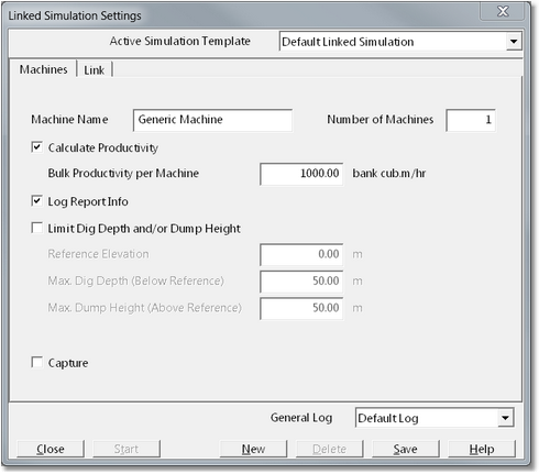
This will open the Linked Simulation Settings dialog box:

Linked Simulation dialog.
Click the New action button on the bottom row of the dialog box to create a new simulation template. This will display a list of current simulation templates and ask you to select one to copy to the new simulation template. A dialog box requiring you to key in the new template name will then be opened. The template name will appear in the Active Simulation Template pull-down list at the top of the dialog box. If several simulation templates exist, these can be accessed via this pull-down list.
A linked simulation assumes the development will be carried out by some (“generic”) earthmoving machine. The productivity will be modelled by the same generic machine.
A generic machine name can be entered into the Machine Name field. This name will appear in productivity reports of linked simulations carried out using this simulation template.
Below the machine name field are the Log Report Info and Calculate Productivity check boxes. Checking the Log Report Info setting tells the system to create and maintain a history of information associated with each application of this simulation template. This report can later be viewed and saved to a file.
The Calculate Productivity check box tells the system to determine total dig machine hours. This calculation is based on machine bulk productivity and the number of machines in the fleet.
These parameters are entered in the Bulk Productivity per Machine and the Number of Machines input fields. The modelled machine hours are determined by dividing the volume excavated and dumped by the total productivity. The total productivity is the productivity per machine multiplied by the number of machines.
The Machines page contains the Limit Dig Depth and/or Dump Height check box. The generic machine/system can limit the excavation depth or dump height relative to a reference height. If you want this limit to be applied, first select the Limit Dig Depth and/or Dump Height check box. Then enter the Reference Elevation, Dig Depth and Dump Height. The simulation will stop if these references are exceeded.
The Capture checkbox will enable auto capture of images. When this checkbox is selected, and the simulation is run, and image of the active window at each stage of the simulation will be captured. The file name and folder for the captured images are set using the menu item Options/Capture Settings.
In the bottom right-hand corner of the Simulation Settings dialog is the General Material Log pulldown list. This pulldown list is used to select the General Log to be used with simulation. When in Free mode the Material Log is set independently by each Excavation and Dump template. However when in Simulation mode Material Log is set by the Simulation Template.
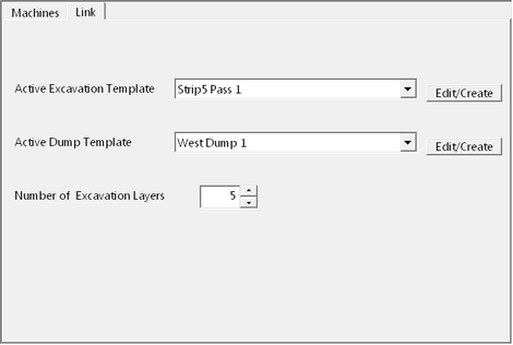
Click the Link page after you have completed entering data into the Machines page, This will open the Simulation Settings Link page:

Linked Simulation dialog, Link page.
The Link page contains two pull-down lists: Active Excavation Template and the Active Dump Template. Use these pull-down lists to select the desired templates. If you wish to edit the templates, or create a new one, click the Edit/Create buttons. This will open the Excavation Settings or Dump Settings dialog boxes.
When the system is in any of the simulation modes other than Free mode, the active excavation and dump templates are set by the simulation template. The active excavation and dump templates set on the link page, as shown above, are locked. While in the Simulation mode, you cannot change the active excavation and dump templates using the Excavation Settings and Dump Settings dialog boxes as accessed via the toolbar. You must use the link page of the simulation dialog box if you want to create or change the active templates.
For simulation to proceed normally, the selected active excavation and dump templates must be “ready” for excavation and dumping. This means that the template parameters have been set as required, excavation polygons drawn and dump shape (point, line or area) also defined and drawn. Details of how to set up the excavation and dump templates are described in earlier sections.
The Number of Excavation Layers parameter sets the number of layers used in a simulation process. The use of these layers is described above.
Click the Save button after all the linked simulation settings have been set. If this step is omitted, you will be prompted to save the altered settings.
The simulation process can be initiated by clicking the Start button on the Linked Simulation dialog box or by closing the dialog box and clicking the Start Simulation toolbar button or the Simulate | Start Simulation menu item:
Start Simulation Toolbar button.
 Key Information - Start Simulation Toolbar button disabled
In order for the Start Simulation Toolbar button to be enabled the following conditions must be met:
•A valid Simulation Template must exist with all relevant parameters set.
•Both Inner and Outer Excavation Polygons for the active Excavation Template selected in the Simulation must exist.
•The Dump Element (point line or area) for the active Dump Template selected in the simulation must exist.
If the above conditions are not met the Start Simulation Toolbar button will be disabled. Note that Excavation Polygons and Dump elements may exist on the topography that they must belong to the templates nominated in the Simulation.
Once the simulation has been initiated, it will progress through the sequential excavation layers and associated dumping. The active terrain window will refresh the excavation after each layer. The dump will be refreshed as specified by the dump template settings. The Esc key or right mouse button can be used to halt the simulation at any time.
Once the simulation has been completed, the excavation polygons and dumps can be moved and/or edited and the simulation process repeated.
The simulation of a large and complex mining sequence may involve many repetitions of the simulation process. Frequently, the excavation and dump settings and constraints will vary throughout the simulation sequence.
For example, you may be simulating a two-pass coal overburden removal operation, part of the sequence excavating to seam 1 and part to seam 2. The operation may use two out of pit dumps, one at a level of 120m and one at a level of 200m. These simulation sequences can be accommodated using one or a combination of the following methods:
1. Create a simulation template for each combination of excavation and dump.
2. Use one simulation template while editing the active excavation and dump templates as required.
3. Create a set of excavation and dump templates for each excavation scenario and activate them as required.
The second method should be avoided if possible. Most scenarios are best handled using a combination of methods 1 and 3. You should attempt to create simulation templates that divides the overall simulation sequence into logical and systematic sub-jobs. This may also provide a more useful simulation log.
It would be logical to divide the above example into a first pass and a second pass simulation. If a series of sub-strips are to be modelled, these templates can be used repeatedly for each strip. Switching between the two dumps is best handled by changing the active dump template as required.
Changing the Active Excavation or Dump templates is readily achieved using the pop-up menu. Pointing to and Excavation Polygon or Dump and right clicking will produce a pop-up menu. One of the items in the pop-up menu is Set Active. Selecting Set Active will make the item active in the Simulation as well as on the topography.