|
<< Click to Display Table of Contents >> Dragline Simulation (Single Step) |
  
|
|
<< Click to Display Table of Contents >> Dragline Simulation (Single Step) |
|
Dragline simulation uses many of the settings and parameters of linked simulations. Please read the linked simulation section before proceeding. The following description assumes that you are familiar with the basic concepts and methods of linked simulation described above.
Dragline Simulation is typically used to model the following aspects of dragline operation:
•Volumetric and Topographic effects. Each major step of the dragline operation is simulated and the material is excavated and dumped to bench or final spoil. As the operation proceeds all volumes (prime and rehandle) as well is an animation of the operation are recorded. This provides a way precisely designing or major steps in the operation, establishing operational feasibility and providing output necessary to communicate the operation to operators.
•Productivity. When used in productivity mode the dragline simulation determines dragline productivity from first principles. Note that achieving accurate productivity requires careful calibration and also demands a high level of detail in the simulation.
3d-DigPlus is most frequently used to model the topographic and volumetric effects of the dragline operation. When productivity calculation is used it is normally based on a subset of the full operation which is sampled and simulated in fine detail.
In order to understand dragline model settings and parameters, it is important to understand how 3d-DigPlus calculates dragline productivity
As in linked simulation, you must create suitable simulation, excavation and dump templates before attempting to model the operation of a dragline. Details of this not covered in the description of linked simulation will be presented later.
Positioning the dragline and matching dragline geometry
The excavation polygons and dump shape used must match the dragline’s geometry. The figure below shows a typical setup:

Dragline Set up for next move.
Simulating the operation of a dragline requires that the dragline is able to reach the material inside an excavation and that it is able to reach the dump area.
If you are conducting a highly detailed simulation, you may wish to model every dragline move. This may for example, involve setting the machine back from the excavation to dig the limits and several steps walking up to the excavation. In such a case, every excavation used must be within the dragline’s dump radius circle.
However for most simulations, it is adequate to place the dragline at an “average” dig position for an excavation. In these cases, it may be acceptable for part of the excavation to fall beyond the machine’s reach at this average position. However, it is important to check that the machine will be able to reach all the excavation at some stage during the operation.
Estimating cycle time
Once a simulation has been set up, the simulation process is initiated, using the Start Simulation toolbar button, as for a linked simulation. The first layer will be excavated and then dumped.
On completion of the first layer, a sample cycle will automatically be simulated and a cycle time estimated. The cycle starts at the bucket engage point. From here, it moves through the fill part of the cycle, then hoist and swing to dump and finally returning to the engage point. Throughout this cycle, the bucket position and trajectory are determined using the dragline geometry, dragline speed parameters and the topography. The bucket is swung and hoisted to reach the dump point as quickly as possible after it reaches the disengage point.
The speed of the hoist system is based on the speeds, accelerations and forces acting on the bucket. The swing time is based on the speed and acceleration of the swing system. As the bucket trajectory is modelled, the system constantly checks to ensure that the bucket is clear of the topography. If the bucket is found to collide with the topography, the cycle is modified to avoid this collision. This will usually involve retarding the swing to allow the bucket to be hoisted clear of the obstacle. The figures below illustrate the geometry of a cycle calculation.

Dragline Simulation, bucket outbound cycle.

Dragline Simulation, bucket return cycle.
Influence of carry envelope
As the full bucket is swung out towards the dump point, the system ensures that it is kept sufficiently close to the boom to maintain a suitable carry angle to prevent any discharge of the payload. This is achieved through a user-defined carry envelope in the plane of the boom.
Bringing the bucket closer to the boom increases the force in the hoist rope and slowing hoist. Hence, the system attempts to hoist the bucket along a trajectory close to the carry envelope. This helps to minimize the hoist force and maximize the hoist speed. If the dragline swings close to a high spoil pile, the topography may force the bucket trajectory closer to the boom, increasing the hoist force and slowing the hoist system. The figure below illustrates the carry envelope.

Dragline Carry Envelope.
Modelling swing, drag payout and hoist lowering
The modelling of swing, drag payout and hoist lowering uses a kinematics approach to determine movement. In this approach, speed and displacement of each system are calculated using a fixed rate of acceleration and a maximum speed.
The top speeds and accelerations for these systems can usually be acquired from manufacturer’s swing and hoist curves. Alternatively, they can be measured on board using a stopwatch. The swing can be determined easily in this manner; hoist and drag payout require a method of measuring the rope lengths that are moved in a given period.
Modelling hoist retrieve
Hoisting retrieve speed is calculated dynamically using approximation. The system does not fully model the electro-mechanical systems of a dragline. However, it does use motor characteristic curves and bucket forces to estimate hoist speed.
As described above, a bucket that is hoisted close to the boom will place greater forces on the hoist system and hence reduce hoist rate. This can be seen in the typical characteristic curve for a hoist motor shown in the figure below. As motor hoist force increases, the line speed decreases.

Hoist motor curve.
Set Simulation Mode
Dragline simulation is selected using the simulation pull-down list or the Simulate | Dragline menu item:

Dragline Simulation Mode.
Set Dragline Parameters
Once you have selected dragline mode, the Machine Parameters toolbar button will become active:
Machine Parameters Toolbar button.
Click on this button to open the Dragline Parameters dialog:

Dragline Parameters dialog.
Click on the New button on the bottom row of the dialog box to create a new dragline. This will display the Copy to New Dragline dialog:

Copy to New Dragline dialog.
Select one of the four default dragline configurations (first four items listed) or an existing dragline. The new dragline will be created as a copy of the selected machine. The new dragline settings and parameters can be modified later in the Dragline Parameters dialog box.
The first page, called the Select page, allows you to select the components of the dragline. Most of these options affect only the appearance of the dragline model. These options are selected via radio buttons.
The Bucket Mass parameter, on the lower right side of the Select page, is used in dragline simulation. This number should be close to the actual bucket mass.
The Dimensions page allows you to set all the dragline’s geometry parameters. These are shown in Figure 94 below.
Most of these parameters are self-explanatory and use standard terminology. Some parameters, such as Maximum Dig Depth and Maximum Dump Height, are used in the simulation process and others affect the appearance of the dragline.

Dragline Parameters dialog, Dimensions page.
 Warning - Dragline Dimensions
The dimensions “House Length” and” Width shoe to shoe” are not used directly in a simulation. However, it is important to enter correct values as these dimensions are used to set the size of the dragline as it appears in a window. It is important that the dragline house is drawn to its correct dimensions so that you can assess the available room on the bench when positioning the dragline. If the house dimensions are too small, it will give you a false impression of the room available for the dragline.
The Movements page contains all the parameters that control the dragline dynamics. It is shown in the Figure below:

Dragline Parameters dialog, Movements page.
Note: The process of fully calibrating 3d-DigPlus for a particular dragline is typically an iterative one. Initially, the best available data should be gathered for all of the above parameters. The results of subsequent simulations then need to be carefully compared with observed productivity measurements and adjustments made.
In practice, a machine cannot be continually operated with all drives at peak efficiency. An efficiency factor, which is input on the Dig & Dump page described below, allows the overall productivity to be de-rated to match the machine’s “average” efficiency.
The carry envelope geometry is entered using the Carry Envelope page:

Dragline Parameters dialog, Carry Envelope page.
The carry envelope, as described above, is a line in the plane of the boom within which the bucket must be kept when hoisting. It is defined by entering a series of discrete points on the envelope as shown above. The definition of these coordinates is shown in the figure below:

Carry Envelope.
The dragline bucket and rigging will determine the carry envelope that you will use. However, for most purposes it is not necessary to have a precise measure of the carry envelope. 3d-DigPlus provides a default carry envelope shape. If this needs correcting, a reasonable estimate can usually be acquired by hoisting a full bucket to various position between disengage and dump points. The bucket should be positioned at a point where any further payout of drag would result in significant payload loss. Photographing the bucket from a “side on” position will usually allow a reasonable estimate of its position relative to the boom.
The Carry Envelope page contains two check boxes: Use in Modelling and Show Carry Envelope. The Use in Modelling setting is on by default. This means that the carry envelope will be used in productivity simulation. The Show Carry Envelope check box allows you to nominate if you want the carry envelope to be displayed together with the dragline on the terrain.
The Dig & Dump page sets parameters associated with bucket filling and dumping. It is shown in the following figure:

Dragline Parameters dialog, Dig & Dump page.
On the right of the Dig and Dump page are the bucket filling and dumping parameters. The first three parameters are Drag Speed, Drag & Fill Time and Drag Distance. These control the bucket filling distance and time. These parameters are related by the equation: Drag time = Drag distance/Drag speed. Only two parameters need to be entered and the third will be determined by calculation.
Spot Time is the time associated with placing the bucket prior to starting the fill. This may be zero. Dump Time is the time lost while dumping.
The Efficiency Factor allows the overall productivity to be de-rated to match the machine’s “average” efficiency. This factor allows for the fact that, in practice, a machine cannot be continually operated with all drives at peak efficiency. The Availability Factor related to mechanical availability.
The above parameters will typically vary with the dig method. At the top right of the Dig and Dump page are four digging method radio buttons. Each of these radio buttons allows the filling and dumping characteristics for the particular dig method to be defined.
The set of dig and dump parameters, as described above, is associated with a dig method. For example in Figure 98, the parameters shown are for a “Key Cut”. Each time you click a dig method button the dig and dump parameters for that method appear in the adjacent input boxes. To enter the parameters for a dig method, first click its radio button, and then enter the parameters.
The “Always show dump radius” and “Always show chop radius” check boxes nominate whether to display circles of these radii together with the dragline on the terrain surface.
At the bottom of the Dig and Dump page is the machine log field. Machine logs are created using the Material | Logged information command. If you check the Log Material box, the Log Name pull-down list will be activated. Using this pull-down list you can select any of the current machine logs. All subsequent volumes dug with this dragline will report to this log.
Machine logs are intended to allow all material associated with a particular machine to be recorded separately from general material logging. If you wish to log material in this way, you should create a new machine log for each machine used. Each machine log should be given a suitable name.
Note: Remember that 3d-DigPlus 2 has three types of material logging: General, Machine and Layer. These are all fully independent. General logging always occurs by default, Machine and Layer logging is optional. Use of Machine and Layer logs is nominated by the user.
The final page of the Dragline Parameters dialog box is the Colors page. This allows you to set the colors of the various machine components. This page is shown in Figure below:

Dragline Parameters dialog, Colours page.
Selection of an appropriate color scheme is important as it can affect the quality of the resultant slide show. If the machine is too dark, it may be difficult to see from a distance. If the machine is too bright, it can stand out from the topography and appear artificial. Check the “Show” button, after selecting the colors, to view the appearance.
Click the Save button when all the dragline parameters have been set, then click the Close button. If the Close button is clicked without clicking the Save button, you will be prompted whether to save the parameter changes or revert to previous values.
Positioning the Dragline
The dragline will be drawn on the topography. You may need to change the view in the current window (zoom out), to locate the dragline. Once you have located it, click the left mouse button, hold and drag to move the dragline to the desired location:

Dragline Positioning.
The final step in setting up the simulation is to create and edit the simulation template. Click on the Simulation Settings toolbar button (make sure the simulation pull-down list indicates dragline mode):
Simulation Settings Toolbar button.
Clicking on the Simulation Settings toolbar button will now open the Dragline Simulation Settings dialog box. This dialog box is shown in the figure below:
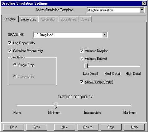
The active template is indicated in a pull-down list at the top of the Dragline Simulation Settings dialog box. It will display “Default Dragline Simulation” if no templates have been created. Although you can use this default template, it is recommended that you create a new one and give it a suitable name.
Click the New button at the bottom of the Dragline Simulation Settings dialog box. This will display a dialog box allowing you to enter the new simulation template name. Once the new template has been created, its name will appear in the Active Simulation Template pull-down list.
The first page of the Dragline Simulation Settings dialog box is the Dragline page. At the top is the Dragline selection pull-down list. This contains a list of all the current draglines. If you have more than one dragline listed, you will need to select one of them from this pull-down list. The selected dragline will be used for simulation with the current simulation template.
The Log Report Info and Calculate Productivity check boxes are at the top left of the simulation dialog box. The default setting for these is on. They tell the system to calculate the productivity and to save the results in a report file.
On the right are the Animate Dragline and Animate Bucket controls for animating the dragline. You have the option of animating the actions of the dragline and its bucket as 3d-DigPlus models an excavation. You can also select the amount of detail displayed by the animation. 3d-DigPlus animates the action by briefly displaying the dragline at various discrete points throughout a cycle. This animation swings the dragline and positions the bucket and ropes. The number of discrete steps shown is controlled by the Detail slider bar immediately below the animation controls.
The Show Bucket Paths check box tells the system to draw the modelled bucket trajectories during the simulation.
Note: The execution of the simulation process will be slowed by the dragline animation. It is recommended that the animation is switched off unless you particularly need to observe the details of sample cycles. Using the Show bucket paths option will display the bucket trajectories with little effect on the simulation time.
The Capture frequency slider bar controls the automatic capture facility that tells 3d-DigPlus to record active window images. These pictures can be assembled into a slide show upon completion of the operation. The slide show system is described later in the Creating and Viewing Animations chapter.
When the auto capture is set to Minimum the system captures one picture prior to simulation and one on completion. The Maximum setting is used to capture a large number of slides to reveal the full detail of every cycle. For most design jobs, the Minimum frequency is most appropriate. Higher frequencies will create an increasingly larger number of files. It is generally only feasible to use high capture frequencies for several excavation blocks.
Create Excavation and Dump Templates
The second page of the Dragline Simulation Settings dialog box is the Single Step page. This controls the simulation settings to be applied to each simulation step:
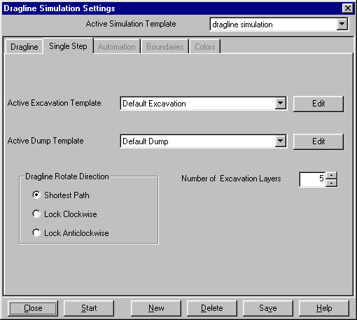
The Single Step page allows the selection of the active excavation and dump templates to be used with the simulation. This is done using the corresponding pull-down lists. If a template needs to be edited or if a new template is to be created, use the Edit buttons. The Edit buttons display the Excavation Settings and Dump Settings dialog boxes.
The Number of Excavation Layers input field controls the number of layers used in the simulation. The default value of five is suitable for most purposes. Increasing the number of layers will resolve the simulation geometry more finely. It may also somewhat slow the simulation process.
The Dragline Rotate Direction group controls the direction of swing rotation. This can be set to always be Clockwise, always Anti-clockwise or to select the rotation direction giving the Shortest Path to dump point on each cycle.
Click the Save button then the Close button after you have completed entering settings for the simulation template. If you click Close without first clicking Save, you will be prompted whether to save parameter changes or revert to previous values.
Create Excavation Polygons and Dump Line/Area
You must create a suitable inner polygon, outer polygon and dump before executing a simulation step.
Apply suitable batters after completing the inner polygon. Next, position the dragline by left clicking and dragging. Finally, place a suitable dump line. Remember you can snap to the dump radius circle. The following figures show this procedure:

Dragline Simulation Set up.

Dragline Simulation Set up.
Using the snap function to create the dump line snapped to dragline boom will precisely locate the dump line. However you can rapidly place at dump line of sufficient accuracy with point and click. Dump lines created in this way can rapidly be repositioned when the draglines moved.
Execute Simulation
Click on the Start simulation toolbar button after the excavation and dump have been defined:
Start Simulation Toolbar button.
The simulation will run and a simulation report will be displayed on completion. This is displayed in the Dragline Performance dialog box shown in the following figure:

Dragline Performance dialog.
As the simulation progresses the data for each simulation step are stored in the dragline simulation report. In addition, volumes of material excavated and dumped are stored in the specified General Log and optionally in the machine log set up for each dragline.
The dragline simulation report data can be viewed in the Dragline Report dialog box. This is opened through the Simulate | Simulation Report menu item:

Dragline Report.
When conducting a dragline simulation for a complete strip a large number of individual moves will be required. Ideally the size of each simulation (i.e. the length of the Inner Polygon and Dump) step should be similar to the actual block size in the pit. However in situations with the dragline has steady-state digging (i.e. away from ramps and endwalls and in areas of regular geology) it is possible to simulate with oversized steps. Providing the length of the excavation and dump are similar, and providing any intermediate bench is fully modelled, it should be possible to get a good estimate of spoil fit and rehandle using oversize blocks. This approach will greatly speed up the simulation process. However it is important not to extend this approach into areas of the strip with highly non-steady-state digging.
An example exercise for a full strip simulation is given in the Single Step Dragline Simulation tutorial.