|
<< Click to Display Table of Contents >> Single Step Simulation |
  
|
|
<< Click to Display Table of Contents >> Single Step Simulation |
  
|
This simulation process involves executing an excavation and then dumping the removed material back onto the topography. The excavation and dumping are both carried out automatically after the user starts the simulation. Simulation proceeds in a piecewise continuous manner. The excavation is executed in a series of excavation layers, unlike a free excavation where the complete excavation is executed in a single step. Once an excavation layer is excavated, the material acquired is dumped. This process involves the following steps:
1.The first excavation layer is excavated in accordance with all parameters and constraints set in the excavation template. The excavated material is placed in the contents of the general material log.
2.Material from the excavated layer is dumped. This material is dumped in discrete parcels in accordance with all parameters and constraints set in the dump template. As each parcel is dumped, it is removed from the General Log contents. Dumping continues until the General Log contents are exhausted (i.e. all the excavated layer material is dumped) or a limiting constraint is reached.
3.The next excavation layer is excavated and dumped.
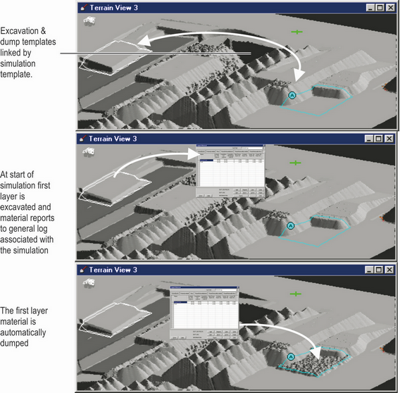
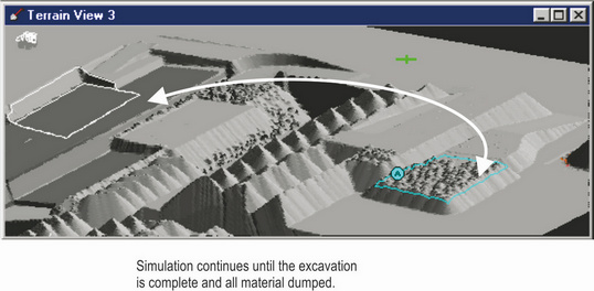
The above steps continue until either all the layers are excavated or a dump constraint is reached. If a dump constraint is reached, any material in the General Log contents (i.e. material that has been excavated but not dumped) is returned to the topography. In this manner, the simulation process always maintains a mass balance (i.e. cut and fill balance). The figures below illustrate a simple linked simulation.

Basic Single Step Simulation.

Single Step Simulation complete.
Single Step Simulation types.
The Single Step Simulation mode has two types Linked and Dragline.
The Dragline mode incorporates a machine model. This machine model assists the user in setting up a simulation that is constrained to the machine’s physical limits. The simulation also estimates productivity. This productivity model uses the machine speeds and operating parameters, together with the intermediate topography as each parcel is dumped, to determine cycle time and hence productivity.
Linked simulation mode performs the same general topographic simulation process as machine simulation. However, it does not directly model the geometry and operating methods of a specific machine. This method uses a more rudimentary and generic method for determining productivity. Productivity is based on a user set rate (volume/hour).