|
<< Click to Display Table of Contents >> Stand-up Blast |
  
|
|
<< Click to Display Table of Contents >> Stand-up Blast |
  
|
This Example involves applying a stand-up blast. This blast produces negligible swell of the in situ material and negligible blast gain.
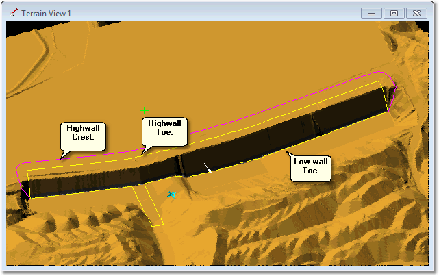
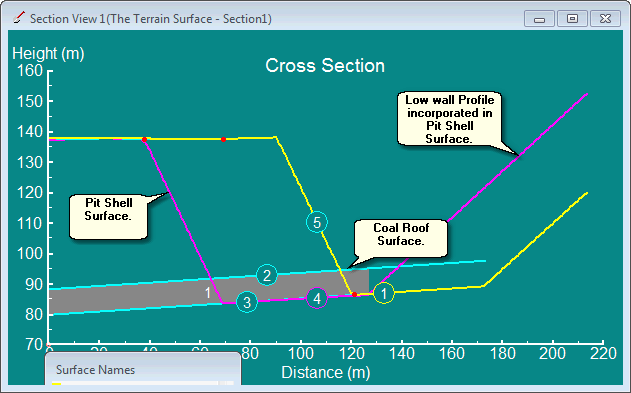
The pit used is the same one used in the previous exercise and the figures below illustrate this pit:

Example Pit for Blast Design.

Example Pit for Blast Design, Section View.
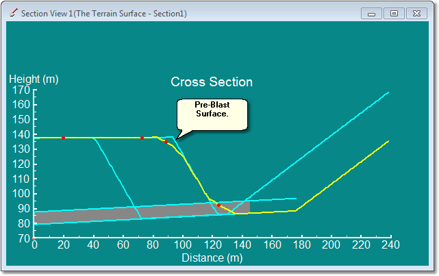
The desired stand-up blast is shown in the figure below:

Stand up Blast Cross Section.
This blast removes a small amount of material from the existing high wall crest and deposits it at the high wall toe.
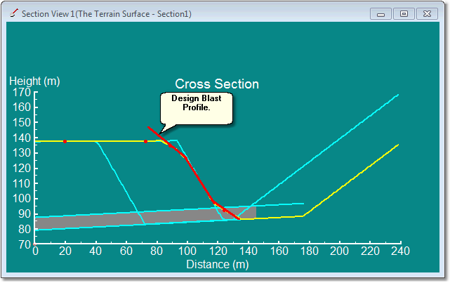
The stand-up blast profile merges with the topography at the top of the high wall. The design Blast Profile required to achieve this blast is shown in the figure below:

Design Blast Profile for Stand-up Blast.
The Design Blast Profile shown above extends above the level of the topography at the top of the highwall. This is necessary as this profile will be applied by Blast Wizard at all the stations over the length of the strip. It is likely that at some of these stations depth of overburden will be greater than that at the section in which the Design Blast Profile is drawn. Hence the Design Blast Profile must extend a little further vertically than is required at the design section. As a consequence of this there is a danger that the Blast Wizard may deposit material on the highwall (under the Design Blast Profile) at some stations. To avoid this we will need to use a Cut Only Polygon ( see section Stand-up Blasts and the use of Cut Only Polygons).
We will perform the blast design twice. The first time the Blast Profile will be created without the use of a Cut Only Polygon. When this design is complete we will undo and redesign the Blast Profile using a suitable Cut Only Polygon. This process will demonstrate the functioning and purpose of Cut Only Polygons.
The following 3d-DigPlus file is required:
Blast_Wizard_Tut_2_Start.3dd
Load this file and follow the steps illustrated in the following video clip: