|
<< Click to Display Table of Contents >> Setting up a Two Strip Operation |
  
|
|
<< Click to Display Table of Contents >> Setting up a Two Strip Operation |
  
|
This example covers the setting up of Automated Excavation and Dumping for two strips of truck and shovel operation.
In this exercise the full automated excavation of two strips, and the linked dumping is set up and run.
The exercise starts at a point where all data (topography, geology and pit design) have been loaded. All steps after this point are covered in the exercise.
To start the exercise load the following 3d-DigPlus file:
Two_Strip_Auto_EX&Dump strt.3dd
To locate this file see the topic Files & Resources for Tutorial Exercises.
The pit used for this exercise consists of 5 strips, each strip being approximately 150 m wide and 650 m long. There is a high wall ramp in each strip and a low wall ramp on the spoil side. Three seams are mined Ate, Boreas, and Chione. This exercise commences at the pit state with Strip 3 Ate and Boreas passes removed and Strip 3 Chione pass intact and ready for excavation. The operation to be modelled is the Strip 4 Ate and Boreas advanced stripping, and the Strip 3 Chione stripping. The figures below illustrate the pit at the start of this operation:
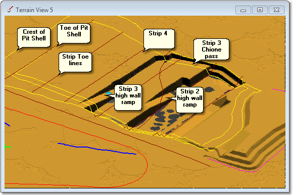
Pit Layout Showing Strips and High Wall Ramps
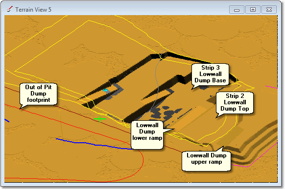
Pit Layout showing Dumps and Dump Ramps
The 3d-DigPlus file includes a set of Pit Shell surfaces for each strip. Each strips Pit Shell surface incorporates a high wall ramp and a low wall profile which forms a Dump in the previous strips void. These low wall Dumps incorporate to ramps as shown in figure above. The lower ramp extends from the pit floor up to the surface at the end wall. And the upper ramp extends from natural surface at the end wall upwards to the top of the dump. The figure below shows the Pit Shell for Strip 3:
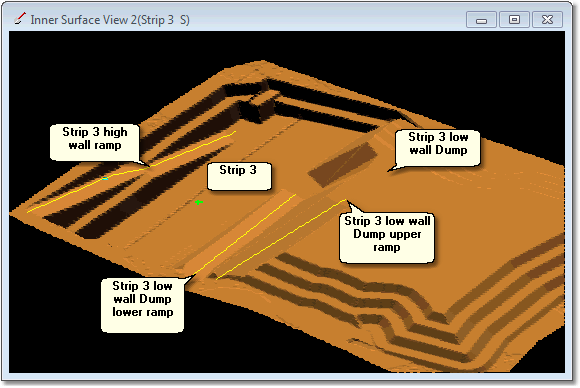
Strip 3 Pit Shell Surface
The Pit Shell has a low wall profile which incorporates a dump surface as shown in figure above. The Dump formed by the surface starts at the floor of the void for the previous strip (Chione seam floor level) extends vertically to a height approximately 30 m above ground level.
For each Strip,the dump surface formed by the Pit Shell is used to build two 3d-DigPlus Dump Templates. The first is called Strip 'n' Lowwall Dump Base, and the second is called the Strip 'n' Lowwall Dump Top. Both these Dump Templates are set up as Staged Dumps and material is dumped progressively in 10 m lifts.
In the Low wall Dump Base dumps the dumping starts at a level of the pit floor and progresses up. Waste from the lower (Chione) passes is hauled across the pit floor and placed in these Lowwall Base dumps.
In the Low wall Dump Top Dumps, dumping commences with trucks at surface level tipping off the end wall. Dumping therefore starts with a lift at the level of the topography along the endwall . When this initial lift is complete dumping progresses up in 10 m lifts to the top of the dump, as defined by the dump surface in the Pit Shell. Ate and Boreas waste is hauled to the surface via the high wall ramp and placed in the Low wall Dump Top Dump for the previous Strip (i.e. Strip 4 Ate and Boreas waste is dumped in the Strip 2 Low wall Dump Top).
The following video clip illustrates the behaviour of these two Dumps types. Both Dumps use the Strip 3 Pit Shell low wall profile as a constraining surface. The first is the Strip 3 Low wall Dump Base, and it commences dumping at the pit floor and progresses up intended or lifts. The second dump is the Strip 3 Low wall Dump Top, and it commences dumping at the topography level at the end wall and progresses up to the top of the dump:
This is illustrated in the following figures:
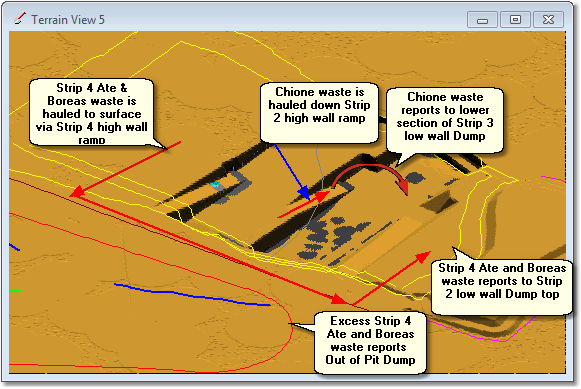
Waste Haulage and Dumping for Strip 4 Advanced Stripping & Strip 3 Lower
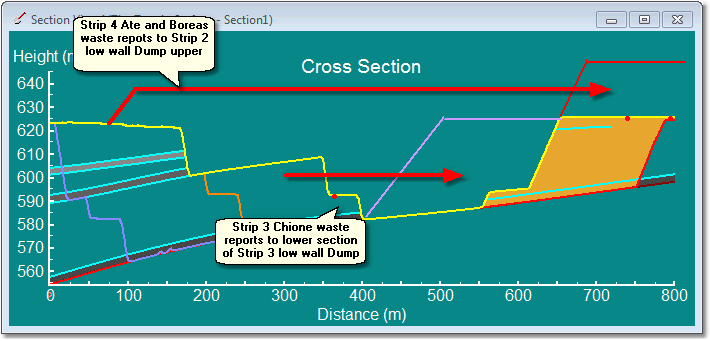
Waste Haulage and Dumping for Strip 4 Advanced Stripping & Strip 3 Lower
Note that Strip 3 low wall Dump referred to in the above figures incorporates a low wall ramp which is used to elevate Chione waste.
The Ate and Boreas waste reports to a Dump Hierarchy where the first dump is the Strip 2 Low wall Dump Upper, when this is full the second dump in the hierarchy is used, Out of Pit Dump 1.
The initial part of this tutorial involves establishing an automated Excavation and Dump Sequence. When complete there will be a Supersequence running Subsequences with appropriate Dump Hierarchy is assigned. At this stage the Excavate Start Supersequence command can be run and all material will be excavated and dumped in sequence. The second part of this tutorial creates and assigns roads and equipment to perform a complete Simulation with productivity.
The steps involved complete the first stage are:
1.Create a Restore point inner surface . As this job will be set up and tested in stages the testing process will modify the topography with excavation and dump. This process usually involves some "debugging" of the Supersequence and assigned Dumps. It is not uncommon when running a Supersequence to find it has some Subsequences out of order, and they either excavate prematurely or late. It is also likely that some dump assignments may be incorrect. It is a simple process to identify and correct these problems however the testing process does modify the topography necessitating restoration. The restore point inner surface saves a copy of the starting topography. Creating a restore point will make the restoration easy.
2.Create a Pit and Block lines. This process creates the block lines which are the basis of Subsequences and Material Logging. These Block lines are associated with a Pit which is created in the same process.
3.Create Staged Excavations, Material Logs, Raw Sequences and Subsequences. There are two strips in this exercise and for each Stage Excavation must be created. Staged Excavation will result in a Raw Sequence, from this the appropriate Subsequences are created. Material Logs are automatically created in this process. Material from each Pass will report to its own Material Log.
4.Create Staged Dumps. Each of the Dumps outlined in the figure is above must be set up as a Staged Dump with appropriate constraining surfaces and staging parameters.
5.Assign Dumps to Subsequences. Once the Subsequences and Dumps are established each Subsequence must have the appropriate Dump Hierarchy assigned in a manner consistent with the strategy outlined in the figure is above.
6.Assemble a Supersequence. Using the Subsequences a Supersequence assembled to excavate each Lift of each Pass in the appropriate order.
7.Run Supersequence and check. At this stage the Excavate/Start Supersequence command can be run in the Supersequence will excavate and material will dump up to the excavation of each Block.