|
<< Click to Display Table of Contents >> Setting up an Excavation Template |
  
|
|
<< Click to Display Table of Contents >> Setting up an Excavation Template |
  
|
Once design file settings are initialized (including the excavation templates and their polygons) repeated excavation consists simply of creating, moving and editing polygons. However, the templates with which these polygons are associated must first be set up.
Before creating a new excavation template you should use Material | Logged Information to create a suitable General Log to handle the excavated material. A pre-defined Default Log always exists in 3d-DigPlus. This log will be used by default if no other log is created and linked into a new excavation template.
Typically the excavation will be conducted for a particular strip of a particular pit and material will need to be logged by block lines for that pit. Prior to setting up the Excavation Template the Pit, Stripand Block Lines should be established using the procedures described in the topic Establishing a Pit and Block Lines.
Creating an Excavation Template
The excavation template contains all the settings and constraints that control the behaviour of associated excavation polygons. Templates are created and edited through the Excavation Settings dialog box.
A template must be created, together with its identifying name, and all its parameters set before excavation polygons are created. A pre-defined excavation template named Default Excavation always exists in 3d-DigPlus. Any number of excavation templates may be created. However, it is best to limit the number to avoid confusion.
New excavation templates are created using the Excavate/fill | Excavation settings command or the Excavation Settings toolbar button:
Excavation Settings Toolbar Button.
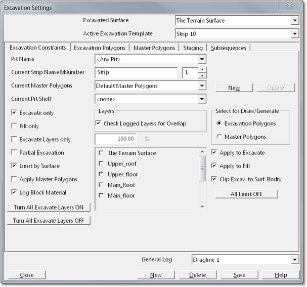
This will open the Excavation Settings dialog:

Excavation Settings dialog - Excavation Constraints page.
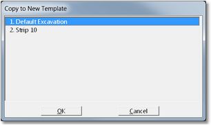
To create a new Excavation Template click the New button at the bottom of the Excavation Template dialog. Note that there is a button labelled New towards the top of the dialog, however the button to create a New template is the one along the bottom row of the dialog. This will produce the Copy to New Template dialog:

Copy to New Template dialog.
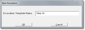
This dialog allows the properties of an existing Template to be copied to the new Template. Frequently new Templates share many properties with an an existing template. Select the appropriate source Template and click OK. Next the New Excavation dialog will be produced allowing the new Template to be named:

New Excavation dialog.
Once the new Excavation Template is established the template settings are set to achieve the desired excavation characteristics. There are three pages of the Excavation Settings dialog which are applicable to generic excavation: Excavation Constraints, Excavation Polygons and Master Polygons.
Excavation Constraints page.
The Excavation Constraints page contains the following elements:
Pit Name pulldown list. The Pit Name pulldown list contains a list of all Pits in the 3d-DigPlus file. When Block Lines are established these belong to a Pit, which is named and created at the time the Block Lines are set up. Pits and Block Lines are required for both Staged Excavations and Block Logging. Note that in order for Block Logging to occur you must also select the Log Block Material checkbox (see below). If the Excavation, for which the template is being established, is to be applied within a Pit for which Block Lines have been set up, then this pit should be selected in the Pit Name pulldown list. If you fail to select the appropriate Pit in the Pit Name pulldown list, 3d-DigPlus will generally determine by location the appropriate Pit for logging purposes. However it is important that the correct Pit is selected in the Pit Name pulldown list, this will ensure that material block logging for the nominated pit will be conducted. If a Staged Excavation is being set up the nominated Pit will be used as part of the staging process and selecting the correct Pit is essential.
Current Strip Name and Number group. This group consists of a name field and a number pulldown list. It allows input of the strip name and number. This name and number is used in various Material Logging and Staging functions.
Master Polygon group. The Master Polygon group consists of a set of items that allow creation and use of Master Polygons. Master Polygons have the same structure and characteristics as the Excavation Polygons described above. However Master Polygons do not directly perform excavations. Instead Master Polygons operate to limit excavations. A common use of Master Polygons is to constrain an excavation to the limits of the Pit Shell. In such cases the Master Polygon will be bound to Pit Shell and the Inner Master Polygon will be drawn to encompass the entire area of the Pit Shell. Subsequent application of Excavation Polygons will then be limited to the pit Shell. Master Polygons were developed for an early version of 3d-DigPlus and have now been largely superseded by the Limit by Surface options.
Current Pit Shell. This option is used in conjunction with Staged Excavations at is explained in the topics under Setting up Staged Excavations.
Excavate Only checkbox. If this checkbox is selected only an excavation operation will be performed. Even if the Inner Polygon is above the topography no fill will occur (see Excavate Only and Fill Only subject above).
Fill Only checkbox. If this checkbox is selected only a fill operation will be performed. Even if the inner polygon is below the topography no excavation will occur.
Excavate Layers Only checkbox. If this checkbox is selected, a conventional excavation will not be performed. Instead all Inner Surfaces which belong to Layers will be excavated in accordance with the excavation settings.
Check Logged Layers full overlap. If Layer Logging is set up, material excavated from such Layers will be logged in the Material Layer Log. In order for this type of logging to be valid it is important that all logged layers are fully separate and independent and do not overlap. If the Check Log Layers for overlap checkbox is selected the system will perform a check to ensure that no Layer overlap occurs.
Partial Excavation checkbox and field. If the Partial Excavation checkbox is selected only a proportion of the full excavation will be conducted. The proportion is specified as a percentage in the Partial Excavation field.
Limit by Surface group. The Limit by Surface group consists of the Limit by Surface checkbox, Limit Type checkboxes and a Surface list. When the Limit by Surface checkbox is selected the Surface list is enabled. Every surface in the Surface list has an associated checkbox. When a surfaces checkbox is selected that surface is used as a Limit Surface as described In the subject Limit by Surface Constraints above. The Limit Type checkboxes are as follows:
•Apply to Excavate. When this checkbox is selected the Limit by Surface constraint will apply to excavate parts of the operation.
•Apply to Fill. When this checkbox is selected the Limit by Surface constraint will apply to fill parts of the operation.
•Clip Excavation to Surface Boundary. When this checkbox is selected excavation and fill operations will be clipped to the bounds of the Limit Surface. If there are a number of Limit Surfaces the excavation will be limited to the intersection of all Limit Surface boundaries.
For most tasks all the Limit Type checkboxes should be selected.
Excavate Layers buttons. There are two Excavate Layers buttons: Turn Excavate Layers on and Turn Excavate Layers off. By default and excavation is performed on the topography only. However by selecting Turn Excavate Layers on the excavation will be performed on the topography and all Inner Surfaces which are used in Layers.
Log Block Material. When Block Lines have been established and logged material is to be subdivided by Block Lines, the Log Block Material checkbox must be selected to engage Block Logging. This checkbox is selected by default, however you should always check to ensure this when setting up a new Excavation Template.
Turn all Excavate Layers On/Off. These buttons turned on or off the excavation of Layers in conjunction with standard Excavation. When the Excavate Layers On option is selected then roof and floor surfaces for all Layers will be excavated along with the Terrain Surface.
Warning Excavate Layers.
 The Excavate Layers function is intended for specialised purposes and not for general use. It is recommended that you do not use this setting unless you are fully familiar with this affects.
General Log pulldown list. The General Log pulldown list contains a list of all General Logs. The appropriate General Log should be selected from this list when setting up the Excavation Template.
Excavation Polygons page
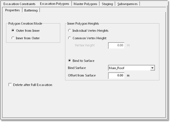
The following figure shows the Excavation Polygon page of the Excavation Settings dialog:

Excavations Settings dialog - Excavation Polygons page.
This page has two sub-pages: Properties and Battering.
The battering page accesses parameters that control the geometry of batter transitions between adjacent polygon segments. For most purposes, the default values usually give satisfactory results, and it is not recommended that these parameters be adjusted. However it if you would like to experiment and batter transitions the parameters on the Batter on page allow this.
The Properties page accesses those parameters that control the basic polygon geometry. On the left side of this page are the Polygon Creation Mode radio buttons. These set the Polygon Creation Mode.
A typical procedure for creating an excavation involves the creation of an inner polygon, then applying batter angles to create an outer polygon. Hence, the outer polygon is a function of the inner polygon plus batter angles. This polygon creation mode is called Outer from Inner.
Excavations can also be created by defining the outer polygon first, and then creating the inner from the outer by applying batter angles and specifying the level of the inner polygon. This polygon creation mode is called Inner from Outer.
When creating excavations in the Inner from Outer mode the outer polygon (from which the inner is created) should be convex, or only mildly concave. Severely concave outer polygons can result in complex crossover of batter projections with unpredictable results.
At the lower left-hand side of the Properties page is the Delete after Full Excavation check box. If this is checked, the polygons are treated as temporary and are deleted after the excavation is performed.
When repeatedly creating excavations using the one excavation template it is usually quicker to retain the inner polygon after each excavation, then move and edit it if required. The outer polygon can easily be created by the batter angles. Hence, it is best to leave the Delete after excavation check box unchecked in most instances.
On the right hand side of the Properties page is the Inner Polygon Heights group. These settings control the shape of the excavation floor.
The Individual Vertex Heights setting allows each inner polygon vertex to be placed with its own height. Each time a vertex is placed for a new polygon, a dialog box will be displayed to key in its height. The heights of points along the inner polygon between segment points are calculated by linear interpolation.
Common vertex height results in all vertices being placed at the same height. The inner polygon will then be on a horizontal plane.
The Bind to surface option binds the inner polygon to an inner surface. Selecting this radio button activates the adjacent Bind Surface pull-down list and Offset from Surface input field. The Bind Surface pull-down list contains all current surfaces, allowing the desired binding surface to be selected.
Binding an excavation polygon to an inner surface results in all points within the inner polygon taking on the shape of the inner surface after excavation. The Offset from Surface field allows the inner polygon (and its interior) to be located at a fixed distance above or below each corresponding point of the bound inner surface.