|
<< Click to Display Table of Contents >> Excavation and Fill Principles |
  
|
|
<< Click to Display Table of Contents >> Excavation and Fill Principles |
  
|
An excavation is created using inner and outer excavation polygons that control the planar shape and extents of the excavation. Other characteristics of the excavation, such as depth and batter angles, are controlled by a range of excavation constraints and excavation settings.
The names inner polygon and outer polygons simply indicate that one polygon is completely inside the other when seen in plan view.
Most mining excavations are defined by the perimeter of the floor of the excavations (e.g. pit design toe lines) and batters. The inner polygon defines the perimeter of the excavation floor. Hence, the usual procedure is to create an inner excavation polygon and apply batters to it that are used to generate the outer excavation polygon.
The user draws the inner polygon interactively and then applies batter angles that generate the outer polygon. After selecting the Excavate/fill | Start command, the material within the polygons is removed from the topography and the excavated volume reported.
Although the Excavate/fill functionality is primarily used to model excavations, the inner polygon can be placed above the terrain to create a fill.
The following figure illustrates these concepts:
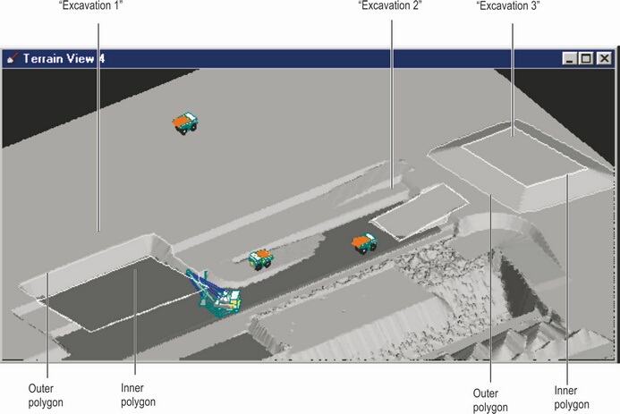
Excavation Templates & Polygons.
The Excavation Template structure is used in 3d-DigPlus to group all the design elements (polygons, settings and constraints) that are used to model the excavation process. Before creating a polygon, the user must create a suitable excavation template and set the appropriate constraints and settings.
Once an excavation template is created it becomes a permanent part of the design file. It can be reapplied and edited repeatedly. Multiple excavation templates may be present in a design.
The inner polygon defines the planar extents of the floor of the excavation. The depth of the excavation is controlled by settings that determine the inner polygon heights. These settings allow a polygon to be placed at a particular height or to be bound to an inner surface.
For example, in figure above, “Excavation 1” is bound to an inner surface that represents a coal seam roof. “Excavation 3” has all vertices at a common height and “Excavation 2” has each vertex at an individual height.
Material is excavated from “Excavation 1” since its inner polygon is below the terrain at all points.
Only fill is added to “Excavation 3” because its inner polygon is above the topography at all points.
Both cut and fill occur in “Excavation 2” since part of the polygon is above the terrain in some areas and below in others.
Once a Inner Polygon is placed the Outer Polygon is usually generated by applying a batter angle to the Inner Polygon. When the batter angle is specified, the system creates the Outer Polygon by projecting at the specified batter angle from the floor of excavation to the terrain surface. Note that prior to excavating, both the Inner and Outer Polygons appear draped on the topography. However when the excavation is complete the inner polygon will be at the floor of the excavation, and the walls of the excavation will incorporate the specified angle. Multiple batter angles can be applied to various sides of and Inner Polygon.
In a typical design, excavations will be constrained to a nominated design surface. This design surface will incorporate all critical batters. Consequently it is not usually necessary to rely on the applied batter angles to generate the correct design batters.
By default, 3d-DigPlus uses combinations of cut and fill as dictated by the inner polygon levels. However, this behaviour can be controlled by settings as shown in the figure below:
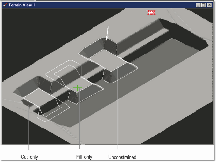
Cut Only & Fill Only settings.
In the above figure, a similar excavation has been applied 3 times.
No limits were set in the “unconstrained” case, and since the polygon is above the terrain in some areas and below in others, a combination of cut and fill occurs.
The excavation was limited to to execute only the fill zone in “fill only” case.
Only the cut zone was executed in the “Cut only” case.
Once and Excavation Template is set up with Inner Polygon bound to the appropriate surface, the user can draw, move and edit the inner polygon and rapidly create a series of excavations. This allows large and complex set of sequential excavations to be conveniently modelled. However, if the resultant total excavation is to conform with a pit design it would require very careful placement and editing of the Inner Polygon for each instance of the Excavation. To avoid the need for detailed placement of individual instances of the Inner Polygon, the Excavation Template structure includes Limit to Surface constraints. In any Inner Surface can be nominated as a constraining surface. Any number of Inner Surfaces can be nominated as constraining surfaces in parallel. When a Excavation Template has a particular Inner Surface nominated as a constraining surface, the resultant excavation will be clipped by a constraining surface. That is to say no excavation will take place outside the bounds of a constraining surface. In several Inner Surfaces are nominated as constraints, the excavation will not extend beyond the bounds of any of these Inner Surfaces.
The following figures illustrate the concept of Limit by Surface constraints. In this example is the file contains a pit Shell for the current strip. The first figure is at the start prior to any excavation of the strip. The Inner Polygon is bound to the roof of the lowest coal seam in the strip. As well as the Pit Shell surface there is also a pre-strip horizon surface.
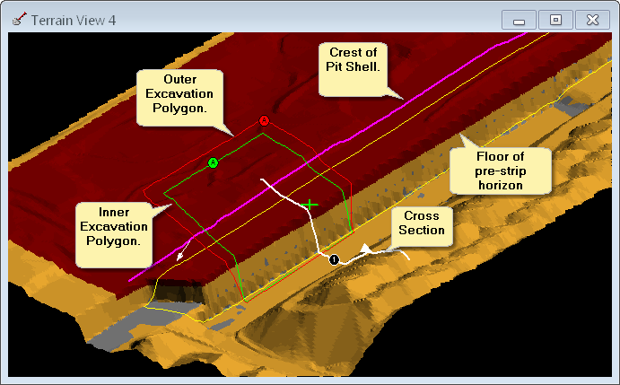
Excavation Constraints example, start of excavation.
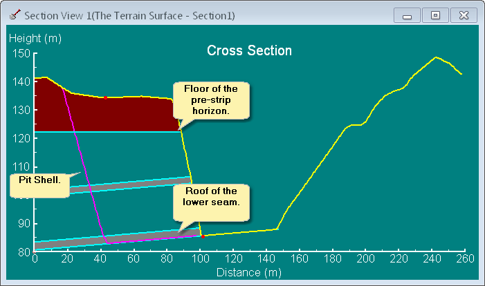
Excavation Constraints Example Start of Excavation - Cross section View.
In the following figure the excavation has been performed with no constraining surfaces. The excavation therefore extends down to the polygons bind surface (roof of lower seam) in a region bounded by the Inner Polygon.
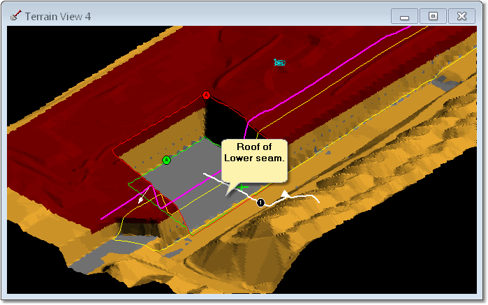
Excavation Constraints example - Excavation complete no limit surfaces.
The Pit Shell surface is now set as a Constraint Surface:
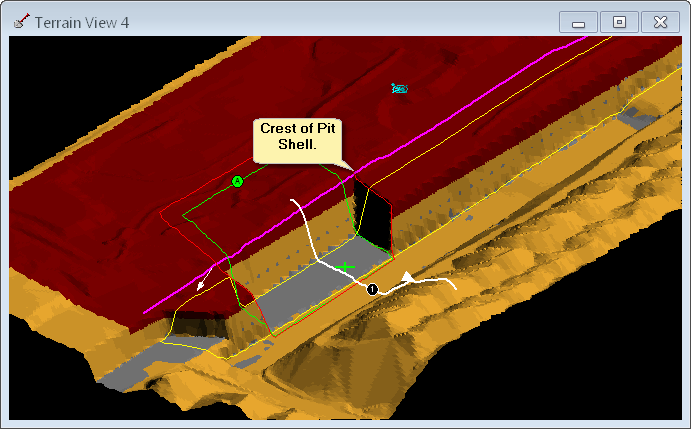
Excavation Constraints Example - Excavation Complete Pit Shell set as Surface Constraint.
It can be seen in the above figure that setting the Pit Shell surface of the constraint effectively clips the excavation to the limits of the design surface.
In the final example pit pre-strip surface is set as an additional Surface Constraint. In this case there are two constraining surfaces, Pit Shell and a pre-strip surface:
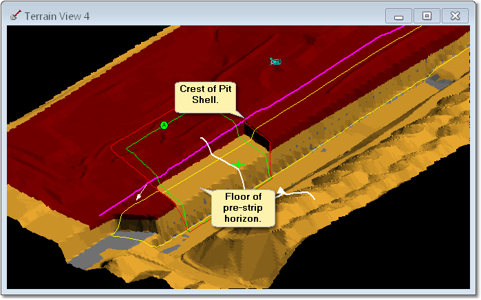
Excavation Constraints Example - Pit Shell and Pre-strip Surfaces set as Surface Constraints.