|
<< Click to Display Table of Contents >> Establishing a Pit and Block Lines |
  
|
|
<< Click to Display Table of Contents >> Establishing a Pit and Block Lines |
  
|
The first stage in setting up an automated excavation sequence is the establishment of a Pit and associated Block Lines. As Block Lines are associated with Pits, Block Lines and Pits are created together. This Process involves naming the Pit and specifying the Block Line spacing, number of Block Lines and orientation. Pits and block lines are established interactively in a terrain window. Once a pit and block line set is established any number of strips can be associated with the pit.
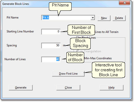
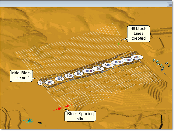
Block lines are created via the Main Menu command Terrain/Block Lines. The figures below show the Block dialog box and the resultant Block Lines for a typical pit.

Block Lines Dialog Box.

Typical Pit and Block Lines.
The Generate Block Lines dialog contains the following elements:
Pit Name Field. The name of the Pit is entered into this field. This name is then used by subsequent 3d-DigPlus processes.
Starting Line Number. This is the Block Line number for the first (lowest numbered) block. Typically this is 0.0 however any number can be used for the Starting Line Number.
Spacing. This is the distance between the automatically generated Block lines. This number is critical as the spacing controls the smallest increment of any automated Excavation. Note that if a fine Spacing is used, the window settings can be used to limit the number of Block Lines which are actually displayed in the Terrain Window.
Number of Lines. This is the number of Block Lines which will be generated, this number needs to be sufficient to ensure that Block Lines span the entire length of each Strip.
There is a checkbox titled Extend Block Lines to all Terrain. By default this box is unchecked and the block lines as they appear on the terrain will extend as far as the first block line drawn by the user. If this checkbox is selected the block lines will extend to the full extent of the Terrain. Generally it is more appropriate to limit the Block Lines to the extent of the first drawn Block Line, extending the block lines to the full terrain can crowd the Terrain Window with too much information. Even when the drawn extents of the Block Lines is limited 3d-DigPlus still extends them internally for block log in simulation purposes. So if an excavation is placed outside the drawn block lines but is intersected by the lines extrapolated this excavation will still be logged and controlled by the block lines.
The procedure for establishing a new Pit and Block Lines is as follows:
•From the Main Menu select Terrain/Block Lines/Create Delate, this will produce the Generate Block Lines dialog.
•In the Generate Block Lines dialog name the Pit and enter the appropriate parameters in the appropriate fields.
•Click on the Draw First Line button. The Generate Block Lines dialog will be temporarily dismissed and the Terrain Cursor will become active in the Terrain Window. Move cursor to one end of the first (lowest numbered) Block Line and left click, then move the cursor to the opposite end and left click. This process produces the first Block Line and as the cursor is subsequently moved an arrow is dragged out. This arrow is used to establish the direction in which the remaining Block Lines will be generated. Drag the arrow to indicate the correct direction and left click.
•The Generate Block Lines dialog will reappear, click the Generate button and the Block Lines will be generated.
Note that this procedure involves the Terrain Window as well as the Generate Block Lines dialog. It is important that the Terrain Window is set up in advance so as to display the full region in which the Block Lines will be created. Before invoking the command to generate the Block Lines, the Terrain Window should be placed in plan view mode, and an appropriate viewpoint established to display the full region of the Block Lines.
The video clip below shows the process of defining a new pit and creating its block lines:
In this example all Block lines are parallel. The system supports Block lines sets with multiple orientations. The procedure as demonstrated in the above video creates a single set of block lines with all block lines parallel. The command for creating block lines can be applied a second time to a pit which has already been created and has some of its block lines. The procedure for pits with sets of block lines of differing orientation is as follows:
•Determine the number of block lines at a given spacing required to complete the first set of parallel blocks.
•Use the above procedure to create this first set of block lines.
•Determine the number of block lines at a given spacing required to complete the second set of parallel blocks.
•Use the Terrain/Create Block Lines/Create Delete command to add this second set of block lines to the already existing pit.
•Repeat this process for as many sets of Block Lines as are required.
Tip- Block Spacing
 In an automated excavation the smallest increment of material excavated is referred to as a Step. Steps are always bounded by the adjacent Block Lines. Hence the block spacing selected when setting up a pit determines the planar extents of the smallest increment of excavation. When setting up block lines it is very important to consider what spacing is required to achieve the desired resolution when subsequently simulating. The block spacing which is typically used for pit design and volumetrics may in some cases be too coarse a spacing for finely resolved simulations.