|
<< Click to Display Table of Contents >> Mine Rehabilitation |
  
|
|
<< Click to Display Table of Contents >> Mine Rehabilitation |
  
|
Rehabilitation of a post mining landscape requires that the typical steep landforms produced by mining are subject to a reshaping process to reduce slopes. Much of this reshaping is typically done by bulldozers. Such bulldozing involves a highly irregular pattern of material movement. Although the 3d-DigPlus bulldozer simulation system was designed primarily for cross pit production dozing it can be adapted to rehabilitation and provide useful information on feasibility and productivity.
To conduct Bulldozer Simulation for a rehabilitation design the following elements are required In the 3d-DigPlus file:
•Terrain in the post mining state. The Terrain Surface should be in the post mining state prior to the rehabilitation design.
•Post rehabilitation design surface.
•An Inner Surface must exist for the rehabilitation design.
•Transportation Analysis. A Transportation Analysis must be conducted to allow Regions to be placed in a manner that balances cut and fill locally.
The post rehabilitation design surface can be produced in another system and imported into the 3d-DigPlus file, however it must have local volume balance in order to be suitable for Bulldozing Simulation. The following figures illustrate these elements:
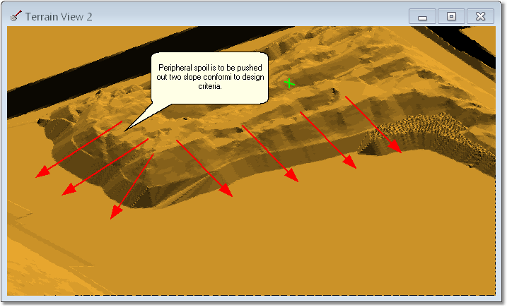
Post Mining Topography (Terrain Surface).
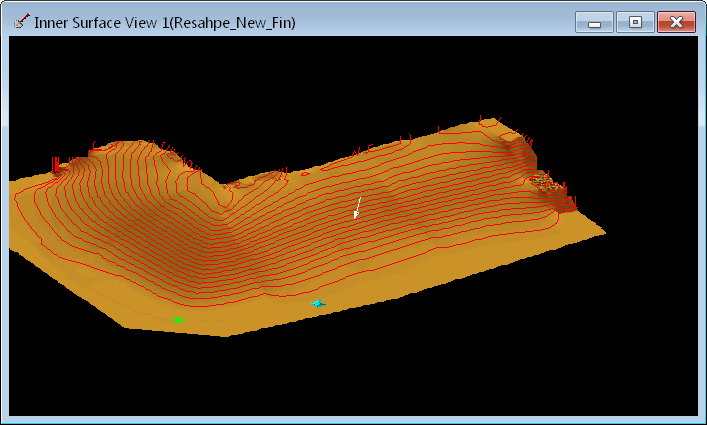
Rehabilitation Design Surface.
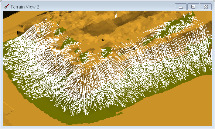
Transportation Analysis.
With the aid of the Transportation Analysis Dozing Regions are created to contain approximately balancing cut and fill. This is achieved by placing regions whose sides run parallel to the arcs and around the limits of the arc arrow heads and tails. When a particular region is complete and focus returns to the Bulldozer Simulation dialog The Cut and Fill associated with the Region is reported in the Each Region group:
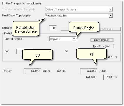
Cut Fill Values for Region.
The following figure illustrates this for the above example:
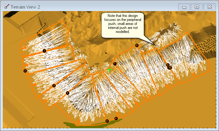
Bulldozer Regions for Rehabilitaion Push.
Once the regions are established the parameters in the Surfaces page must be set up. It is typically the case with rehabilitation pushing that only excavate surfaces are required and appropriate. The following figures illustrate this and demonstrate the typical process of pushing down spoil. These figures show the progress of the bulldozing operation at three stages throughout the task. Only Excavate Surfaces are used in this example:
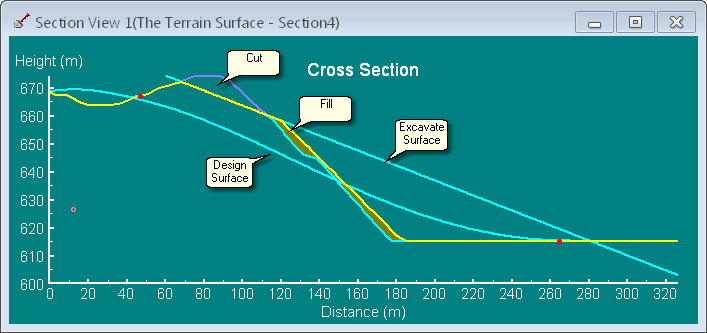
Cross Section through Rehabilitation Push – Initial Stage of Operation.
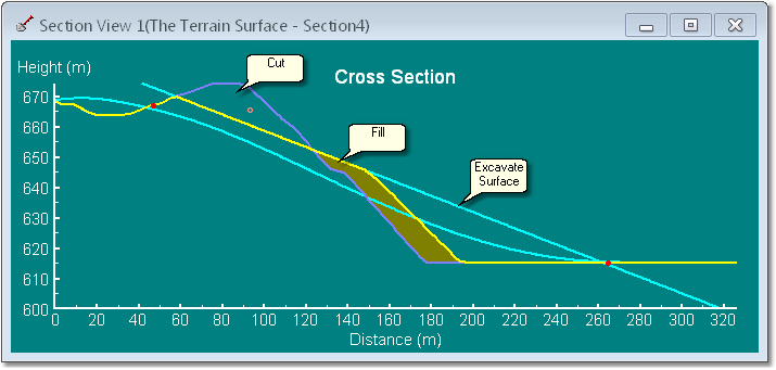
Cross Section through Rehabilitation Push – Mid Stage of Operation.
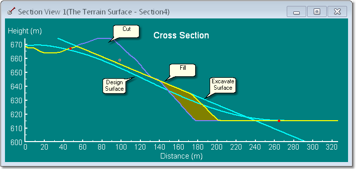
Cross Section Through Rehabilitation Push – Final Stage of Operation.
As can be seen in the figures above the Excavate Surface gradually extends to the point where it merges with the Design Surface with little potential to incorporate a Bridge Surface or Dump Surfaces. Situations may occur within rehabilitation pushing were dump surfaces may be used, however typically only Excavate Surfaces are required.
Figure below illustrates typical Surfaces page set up for rehabilitation push simulation:
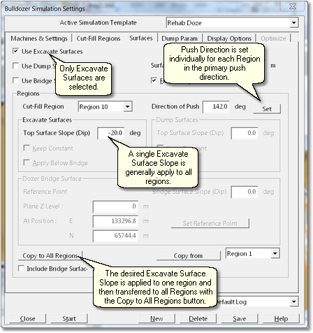
Typical Surfaces Page Setup for Rehabilitaion Push.
The settings Dump Parameters and Machines and Settings pages should be set up as described for the cross pit push in the previous topic.
As rehabilitation push is always in fill material, a Material Log should be established with a Swell of 1.0. This log should be selected when setting up the Bulldozer Simulation.
Running a Mine Rehabilitation Bulldozer Simulation
Simulation of a bulldozing in rehabilitation push is fundamentally different to that for most production pushing. This is due to the fact that in production pushing is typically possible to ensure that there is a small excess of spoil room to every region. Hence the simulation should complete with the excavation for each region completed and all material dumped in the available spoil room. In rehabilitation pushing cut and fill must balance exactly. When dividing the total area into regions it is impossible to ensure perfect cut fill balance within the regions, as described above an error of around 5% must often be accepted. As a consequence of this most regions or complete with either a small amount of excavation left in place or a small void on the spoil site. These effects generally have only a small effect on productivity estimates. However each instance should be assessed individually for the significance of any error.