|
<< Click to Display Table of Contents >> Excavation Modelling & Material Logging |
  
|
|
<< Click to Display Table of Contents >> Excavation Modelling & Material Logging |
  
|
The principles of excavation modelling in 3d-DigPlus are explained in detail in the topic Excavation & Fill Modelling.
An excavation is defined using an inner polygon and an outer polygon, which control the planar shape and extent of the excavation. A set of excavation constraints and excavation settings controls other characteristics of the excavation, such as depth and batter angles. Most mining excavations are defined by the perimeter of the floor of the excavations (pit design toe lines) and batters. The Inner polygon defines the perimeter of the excavation floor. The usual design process is to create the inner polygon and to generate the outer polygon based on excavation batter angles.
Material quantities (volumes of material excavated and dumped) are logged in a data base known as the Material Log. Any number of Material Logs can be defined by the user and each log has its own characteristics (swell factor density etc). All excavated material reports to a nominated Material Log.
Excavation Polygons belong to a structure called a Excavation Template. The Excavation Template defines various characteristics of the excavation including excavation constraints, depth of excavation and Material Log. Any number of Excavation Templates can be created. Typically an Excavation Template is created for each equipment fleets and or excavation pass.
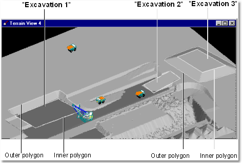
The figure below illustrates some typical Excavation Polygons:

Excavation Polygons.
In the above figure the Inner Polygon for Excavation 1 is bound to a coal seam roof. The Excavation Polygon for Excavation 2 is bound to a ramp design surface. The Excavation Polygon for Excavation 3 is located a fix level. Each set of Excavation Polygons belongs to a particular Excavation Template.
It can be seen that Excavation 3 is actually above ground and creating a dump. Dump design in 3d-DigPlus is typically done using a specialised dumping system. However the Excavation functionality can be applied in a manner that creates a dump. The functionality is actually called "Excavate/Fill" as it can be used to create fill zones.
The floor of the Excavation is defined by the Inner Polygon. There are three modes of setting the level of the floor of excavation:
•Bind to Surface. This is the most common mode whereby the inner polygon is bound to a nominated Inner Surface. The Inner Polygon itself as well is all of the area within the inner polygon is registered to the Design Surface.
•Common Vertex Height. This option excavates to a fixed level with the level being defined by the parameter Common Vertex Height.
•Individual Vertex Height. With this option the user must nominate the excavation level of every vertex on the Inner Polygon which is created.
The following two videos clip illustrates the basic Excavation procedures. The fist clip demonstrates the basic excavation procedures, the second introduces Excavation Constraints.
Basic Excavation procedures.
During this exercise you will be prompted to save a file called 'PreStrip_Start', it is important to save this file and this is required for a later exercise.
Load the previously saved 3d-DigPlus file:
Gen_Train_4.3dd
Excavation Constraints.
Load the previously saved 3d-DigPlus file:
PreStrip_Start.3dd