|
<< Click to Display Table of Contents >> Setting up Excavators |
  
|
|
<< Click to Display Table of Contents >> Setting up Excavators |
  
|
New excavators are created via the Excavator Parameters Dialog Box. Excavator parameters input in this Dialog box allow the creation of a type of excavator. Any number of excavators of this type can be added to the fleet. Once set up and calibrated an Excavator type can be saved as a file and used in other 3d-DigPlus sessions.
Excavators are set up by firstly creating a set up for an excavator type. The type is equivalent to excavator make, model and bucket capacity. If several excavators of a particular model and bucket capacity exists the type is set up and the number is set to the number of such excavators available for a particular operation.
To set up a new excavator type firstly ensure that the Simulation Mode pulldown list is set to Truck (truck & shovel):
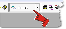
Simulation Mode Pulldown set to Truck
Click on the Create Machines toolbar button.. This button is a pulldown and includes options for Truck and Excavator, select the Excavator sub button:

Truck & Shovel setup pulldown
This will bring up the Excavator Parameters dialog. If no other Excavators exist in the 3d-DigPlus file most of this dialog will be disabled except the New Type button:

Excavator Parameters dialog with no Excavators present
If Excavators already exist in the 3d-DigPlus file these will appear in the Excavator Type Name pulldown list (see figure above).
To create a New Type Excavator click on the New Type button. This opens the Copy to new Excavator dialog:
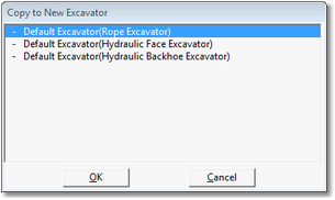
Copy to new Excavator dialog
The Copy to new Excavator dialog lists all Excavators in the 3d-DigPlus file. If this is the first Excavator created there will just be the three default types as shown in figure above. If user defined Excavators have been created these will appear in the list. One of the default or predefined Excavators must be selected and it settings will be copied to the new Excavator type. The three default Excavator Types include rope shovel, hydraulic face excavator and hydraulic backhoe excavator. Click on the most suitable Type and click OK. A new Excavator Type will be created with characteristics the same as the base type selected. The fields in the Excavator Parameters dialog will contain the Parameters copied and all will be editable. The set up now involves setting appropriate parameters.
The first task is to give the new Excavator Type a suitable name and to set the number of machines of this type. This is achieved by keying the name into the Name field and entering the number of the type in the New Number this Type field:

Excavator Parameters dialog Excavator name and Number fields
Note that the number of Type can be changed at any time. It is recommended that the name indicates Excavator make and model.
Once the new Excavator Type is established its parameters must be entered into the fields on various pages of the dialog.
Setting Excavator Category
The first page of the dialog is the Select page. This page allows selection of an excavator category from the three available:
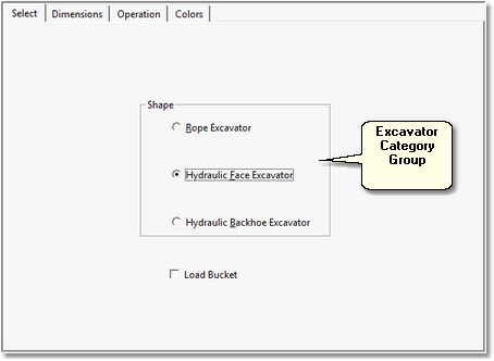
Excavator Parameters dialog Select page
The excavator category to match the machine been set up is selected on this page.
Setting Excavator Dimensions
Excavator dimensions are input on the Dimensions page:
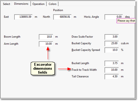
Excavator Parameters dialog Dimensions page
At the top of the Dimensions page are three fields, East, North and Horiz Angle. These give the current location and orientation of the machine. The position of the machine is set up interactively by the user prior to simulation, and automatically during simulation. So these fields do not usually require user intervention.
There are two groups of fields labelled Excavator dimensions in the figure above. These fields control various dimensions of the excavator. They only influence the appearance of the excavator model and do not affect productivity. There is a field called Draw Scale Factor, this factor increases the size of the excavator as it appears on the terrain. With a Draw Scale Factor of 1 the excavator will appear at its actual size relative to the topography. Frequently this size is too small to be readily visible during simulation and Draw Scale Factor of between 2 and 3 is recommended.
The Bucket Capacity and Bucket Capacity Spread a very important parameters as they are critical to productivity. The Bucket Capacity is the nominal capacity of the bucket in bank cubic metres. This should be an estimate of the average bucket load for a particular machine. The Bucket Capacity Spread, expressed in percent, controls variability from load the load.Using this parameter a Monte Carlo simulation is performed so that bucket load varies in a similar manner the variation in the field. The Bucket Capacity and Bucket Capacity Spread influence productivity via truck load. The load of each truck simulated is determined by these parameters plus the truck parameter called Fill Threshold (see following topic on truck set up).
Key Information Truck Parameters, Excavator Parameters, Material Properties and productivity
 The Truck Parameters, Shovel Parameters and Material Properties all influence fleet productivity.
The weight of material in each bucket load delivered to the truck is determined by the density of material excavated and the individual bucket load.
The density of material in the Excavator Bucket is determined by the Density parameter in the Material Log associated with the Subsequence being excavated.
Each individual Excavator bucket load is determined using the Bucket Capacity and the Bucket Capacity Spread.
The total payload of the truck is determined by the individual bucket load is calculated and Truck Fill Threshold.
Setting Excavator Operational Parameters
The Operation page of the Excavator Parameters dialog allows input of parameters to determine the relative position of excavator components and also Excavator cycle time.
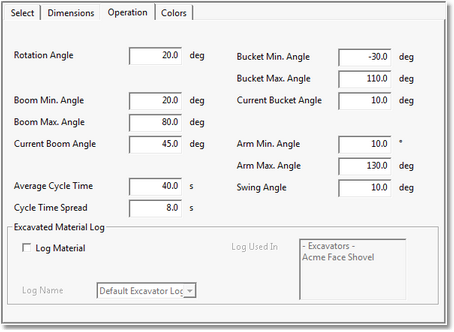
Excavator Operational Parmeters
The majority of parameters are self-explanatory and control the attitudes of the movable components of the Excavator. It is generally not necessary to adjust these parameters and the default settings are nearly always adequate. Adjusting these parameters can be useful when acquiring features requiring very high detail such as equipment operation manuals. For example an excavator can be put into a position where it is about to discharge into a truck and a truck can be located under the bucket.
In the bottom left corner of the Excavator Operation page are the Average Cycle Time field and the Cycle Time Spread field. These parameters are very important and critically affect productivity. Estimates of Average Cycle Time can either be acquired from historical data all machine specifications. to determine the representative Cycle Time Spread requires a detailed study of the machine. Information is often available expected cycle time spread is. The default setting is 20% and in the absence of any better information this setting is recommended.
Setting Excavator Colours
the Colour Page of the Excavator Settings dialog allows the colour of the excavator components to be set
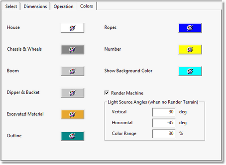
Excavator Settings dialog Colour page
The default colours are generally adequate, however it is important in simulation that the Excavator can be clearly seen and generally brighter colours the greater contrast with the terrain base colour work best. At the bottom right corner of the Excavation Parameters dialog is the Show button. Clicking the Show button will produce a temporary window showing the excavator rendered the selected colour scheme.
The Colour page includes the Render Machine checkbox. When this box is unchecked Excavator will be drawn in wireframe. When it is checked machine will be fully rendered. When the view is zoomed out from the excavator machine will always appear in wireframe mode. The default setting is for the Brenda Machine checkbox to be checked so machines will be fully rendered. There is generally no need to change this default setting. However if there are three large number of rendered machines, and 3d-DigPlus is running on a slow computer rendering machines can compromise refresh time.
Once all the necessary settings have been input for the Excavator click the Apply button. This will apply the settings to the current Excavator type.
Once an Excavator is properly set up and calibrated the Excavator Type can be saved to file for use in other 3d-DigPlus sessions. From the Main Menu go File/Save As. From the Save as type pulldown list at the bottom of the Filer, select the file type Excavator Data (*.xcv):

File Save As Excavator
This will save a file to disk with all the Excavator type information. This file can be loaded in other 3d-DigPlus sessions to recreate the Excavator type.