|
<< Click to Display Table of Contents >> Performing an Excavation |
  
|
|
<< Click to Display Table of Contents >> Performing an Excavation |
  
|
The following description applies to the modelling of an excavation in the Free simulation mode. Set this mode from the menu item Simulate | Free Excav & Dump, or use the pull-down list setting on the toolbar:

Simulation Mode pulldown, Free mode.
Create Excavation Template
A suitable excavation template should be created as described above prior to the modelling of an excavation. Open the Excavation Settings dialog box. Use Excavate/fill | Settings or click the following toolbar button:

Excavation Settings Toolbar button.
Set up a suitable Excavation Template as described in the previous topic or use the Active Excavation pull-down list to select the desired excavation template and click the Save button, then the Close button.
Draw Inner Polygon
Next, we create the inner polygon. Select the Draw Inner Polygon button:
Draw Inner Polygon Toolbar button.
The Terrain Cursor will become active on the terrain in the current window. The inner polygon is now drawn interactively with the mouse. Surface features and other objects may be snapped to in this process (see Manipulating Vector Objects). Click the right mouse button to close the polygon when all vertices have been placed. You can use the vector objects editing techniques to adjust the shape as required. The figures below illustrate this procedure.
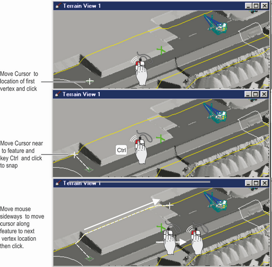
Drawing an Inner Polygon.
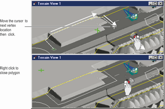
Completing an Inner Polygon.
Note: The inner polygon always appears draped on the topography. However, the floor of the excavation it defines will be at the surface nominated by the excavation template.
Apply batter angles to Inner Polygon
Having drawn the inner polygon, the outer polygon is now created by applying batter angles. One inner polygon can have several different batter angles applied to different parts of its perimeter. However, only one batter section can be set at a time. Initially we must apply one angle to the full perimeter. Adding extra angles involves replacing this initial batter in those segments requiring a different angle. Start the procedure by selecting the Define all by Angle toolbar button:
Defined All by Angle Toolbar button.
A dialog box will be displayed to allow you to enter the desired angle:
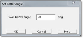
Set Batter Angle dialog.
Key in the desired angle and click OK. The outer polygon will be generated:
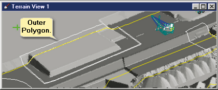
Outer Polygon.
Note that in the above diagram part of the Inner Polygon is placed on the coal seam surface to which this polygon is bound. In these areas the topography is already at the level of the floor of the excavation. Consequently no batter is required in this area and both Inner and Out are Polygons are coincident. However in areas where the topography is above the floor of excavation the Outer Polygon appears distinct from the Inner Polygon.
The batter angle is defined as the angle between the horizontal plane and the batter slope as shown below:
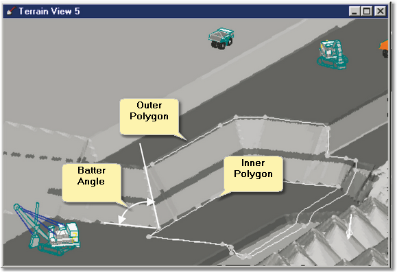
Batter Angle Definition.
Frequently Inner Polygon will require a number of different batter angles on various sites. To apply additional Batters the first step is to apply a single batter to the full polygon as described above. Subsequently segments of the Inner Polygon can have differing batter angles applied. This is achieved using the Define by Angle command which is accessed by the Define by Angle toolbar button:
Defined by Angle Toolbar button.
Note that this button is only accessible if an initial batter is already in place, as described above. After selecting the Define by Angle command, the terrain cursor will snap to the active inner polygon. Sideways mouse movements will cause the cursor to track around the polygon. Moving the mouse to the right causes cursor movement in one direction around the polygon (clockwise), while movement to the left moves the cursor in the opposite direction (counterclockwise). Up and down movement of the mouse can be used in place of left and right movement, However it is recommended that only sideways mouse movements are used.
 Key Information - Marking Inner Polygons and other vector objects.
The procedures described here for marking portion Inner Polygons for specific battering, are common to many vector object procedures. If the principles are understood the process is quite efficient. However new users often try to "push" the cursor in 3d. This process will not work and users are advised to confine mouse movement to SIDEWAYS movements. Right mouse movements track cursor clockwise around the object, left mouse movements track the cursor counterclockwise.
To redefine a batter, move the cursor to the start of the segment and left click. Sideways mouse movement will continue to move the cursor, but now the polygon will be highlighted as the cursor traverses over it. Highlight the section to apply a new batter and left click. The batter angle dialog box will be displayed. Input the batter angle to apply it to the highlighted section. Select the OK button and the new batter will be applied. The following video clip illustrates this procedure:
Perform excavation
Once the inner and outer polygons are complete, you may run the excavate command to perform the excavation. This command is accessed via its toolbar button:
Start Excavation Toolbar button.
The material will be excavated, the terrain updated and a report presented:
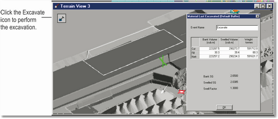
Excavation Complete.
Move and re-apply excavation
If the excavation template was set up with the Delete after Full Excavation (Excavation Settings, Excavation Polygon page) option switched off, the polygons will remain after the excavation is completed. The inner polygon can be moved and edited (see Manipulating Vector Objects). Once this editing has been completed, click the Generate Outer Excavation Poly button to create an outer polygon:
Generate Outer Polygon Toolbar button.
A new excavation can now be executed. This process is shown in the following figures:
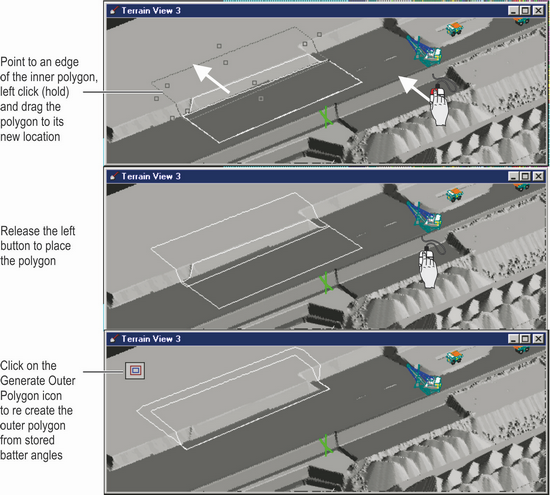
Moving Excavation Polygons.

Excavating at new location.
After an excavation has been completed, the material that was excavated reports to the General Material Log associated with the template. It is important to understand how these volumes are treated in the material log.
The volume between the pre- and post-excavation surfaces is determined after the execution of an excavation. This volume is split into prime and rehandle volumes. The calculated prime volume is reported and logged as the prime bank volume (bank cubic metres (BCM) or bank cubic yards (BCY)). This prime bank volume is multiplied by the swell factor (from the active log) to give the prime swelled volume (loose cubic metres (LCM) or loose cubic yards (LCY)). The rehandle volume is loose in situ, so this volume is reported as the swelled rehandle volume. This swelled rehandle is divided by the swell factor to give the bank rehandle volume.
If the inner polygon is below the topography at all points, or if the Excavate only constraint is set, the operation results in only excavation of material (i.e. no fill). The total volume of the excavation is added to the contents and cumulative cut columns in the material log
If the inner polygon is above the terrain, a fill operation is performed. The volume between the pre- and post-fill surfaces is determined. All this material is assumed to be non-prime (i.e. it was deposited by a fill operation and hence was not prime in situ material). The volume is divided by the swell factor to give the bank volume. As this is a fill operation, the volume is shown as negative. The fill volume is subtracted from the contents column of the material log and added to the cumulative fill column.
If the inner polygon is below the topography in some regions and above in others, a combination of excavate and fill is performed. Material is split into cut and fill components. Each component is then treated according to the above procedures.
Each time an excavation is performed (i.e. every time the Start Excavation command is initiated) and item is created in the Material Log is history. When this history is accessed via the Material Log dialog all items in the history are presented at each individual excavation will appear in chronological order. For each item in the history the excavate or fill volume is recorded.