|
<< Click to Display Table of Contents >> Creating a new Road with horizontal and vertical alignment |
  
|
|
<< Click to Display Table of Contents >> Creating a new Road with horizontal and vertical alignment |
|
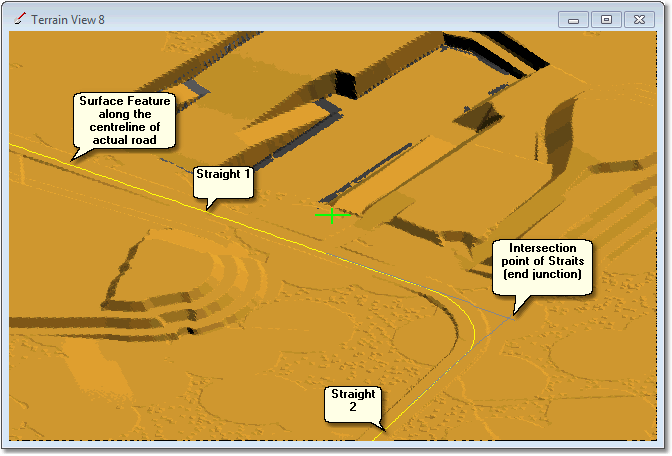
This topic covers the basic procedure for creating a new Road. The process of creating a new road is illustrated in this topic using an example which involves a Main Haul Road. This road exists on the topography and can be seen in the rendered terrain model. The following figure illustrates the pit and the haul road to be modelled:

Before creating any roads, the network of roads required and their extents must be determined. In the above figure material will be hauled from the pit shown and transported to the local dumps all of which can be seen in the figure. Consequently the extent of all necessary roads is limited to the area shown.
The centreline of the haul road is shown as a yellow Surface Feature. The formation of the road can also be seen on the terrain. The haul road extends well beyond the region shown in the above figure, however only a small subset of this road is required to model the local haulage needed for the proposed simulation, the limits of the road needed for modelling are indicated above by the eastern and northern limits.
When creating this haul road the yellow feature line will be used as a guide for creating the horizontal alignment, which will run from the eastern limit around the corner to the northern limit.
The Create Roads dialog is accessed by clicking on the Create Roads toolbar button:
This opens the Create Roads dialog. In the top right corner of the Create Roads dialog the New Road button creates a new road:
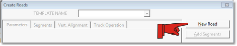
Once the road is created the fields in the Create Roads dialog box become active:
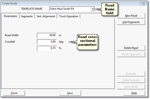
The newly created Road is given a default name that appears in the Road Name field. This field is active and the default name should be replaced with a suitable descriptive name. As a large simulation may have many Roads, is important that Roads are given names which makes them clearly identifiable. As Roads will either be Main Haul, Excavation Access, Dump Access, it is generally best to either include the full road type description in the name or use a suitable acronym (e.g. Strip 5 Excav Access). In this example the name given is Main Haul South Pit.
Horizontal Alignment
Having created and named the new road the next task is to create the Horizontal Alignment.
The Create Roads dialog box has four pages, it opens on the Parameters page. This page has three fields which define the Road's cross-sectional parameters. These parameters are only used if the road is to be excavated. Road excavation is used to impose a new (currently non-existent) road design on the topography. Typically most roads modelled either exist on the survey topography or are part of the strip design and dump design. Consequently excavation is not normally required and hence these parameters do not need to be input. The use of Roads Excavation is covered in the tutorial Using the Excavate Roads function.
A Road consists of a series of Straights. The point where two Straights join is referred to as the End Junction. Contiguous group of Straights is referred to as a Segment.
The the Segments page deals with parameters and settings that are specific to each segment. These parameters and settings are:
Cut Batter Angle. In parts of the Horizontal Alignment where the proposed road is below natural ground level Cut Batter Angle determines the angle placed between the edge of the road Formation and the surrounding topography. This parameter is only relevant when the road is to be Excavated.
Fill Batter Angle. In parts of the Horizontal Alignment with the proposed road is above natural ground level, the Fill Angle determines the angle placed between the edge of the road Formation and the surrounding topography. This parameter is only relevant when the road is to be Excavated.
End Junction.The End Junction refers to the transition placed between two adjoining Straights. This can be either a point of intersection between the Straights, or a curve. The End Junction page is detailed below.
The use of Segments is to allow the above parameters and settings to be applied differently to different parts of the Road. Where a Road is to have two or more segments the procedure for creating the multiple segments is:
•Set parameters for the first Segment, use the Add Segments button to create the Horizontal Alignment portion for this Segment.
•Modify the parameters as required for the second Segment, use the Add Segments button to create a Horizontal Alignment portion for the second Segment.
•Repeat the process for all required Segments.
When they Add Segments button is clicked the Create Roads dialog is temporarily dismissed and the cursor becomes active in the Terrain Window. The procedure is to move the cursor to the starting point of the first Straight and left click to start, move the cursor to the end of the first Straight and left click to complete this Straight, then repeat the process until the desired Horizontal Alignment for the Segment is complete. After placing the final point right click to finish and return to the Create Roads dialog.
For the majority of roads used in simulation a single segment will adequately cover the entire road. Note also that as Excavate Road is not typically used the Cut Batter Angle and Fill Batter Angle parameters are typically not relevant.
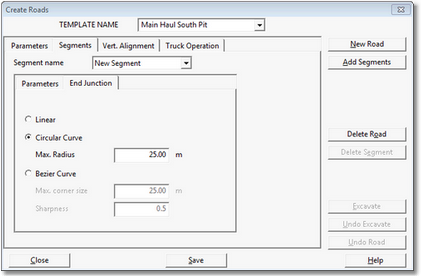
The End Junction page contains parameters settings which control the way in which the junction between two Straights is formed:
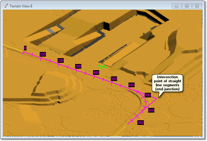
The figure below illustrates the concept of straight line segments and segment junctions:
The Linear end Junction option joins the two segments at a single point with no transition:
A single point linear Junction is clearly an unsatisfactory way of modelling the above curve. However if the curve have been subdivided into a number of Straights with linear Junctions the result would have been adequate.
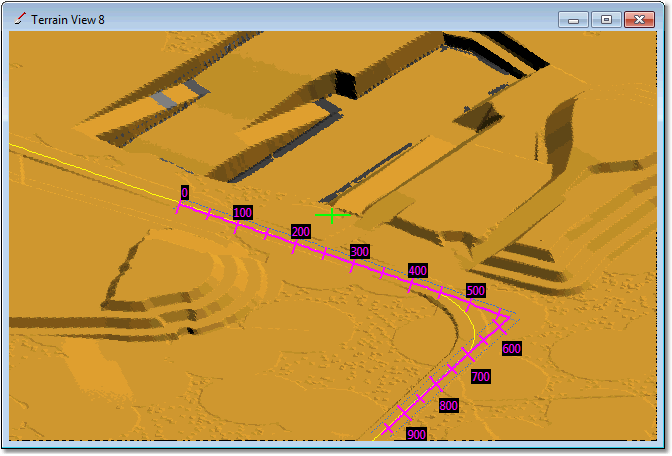
The Circular Curve option places a circular curve of specified radius between the two segments:
The circular curve gives a very close fit to the actual road centreline.
Bezier curves produced a similar looking result to circular curves.
In the above examples the circular curve gives a greatly superior result to the linear junction. However to achieve this good fit with a circular curve requires knowledge of the curve radius on the actual road, and the location of the intersection points of the Straights between which the curve is placed. Generally when placing roads in 3d-DigPlus file this information will not be available. A fast and adequate way modelling curves is to approximate them with a number of Straights. This can be achieved with the Linear option, however the default End Junction type is circular with a 25 m radius. 25 m is less than any curve which will occur a road and consequently when using this option an actual curve is modelled with a series of straight line segments connected with this default radius. The result is a reasonably smooth corner which adequately models the actual road.
The following video clip illustrates construction of the two segments in the corner using firstly a full circular curve junction set up to match the actual road, and secondly a series of segments around the corner with 25 m radius junctions: