|
<< Click to Display Table of Contents >> 3d-DigPlus Interface |
  
|
|
<< Click to Display Table of Contents >> 3d-DigPlus Interface |
  
|
3d-DigPlus is started by clicking on the desktop icon:

Alternatively 3d-DigPlus can be started using the window's Start button and selecting the 3d-DigPlus program group.
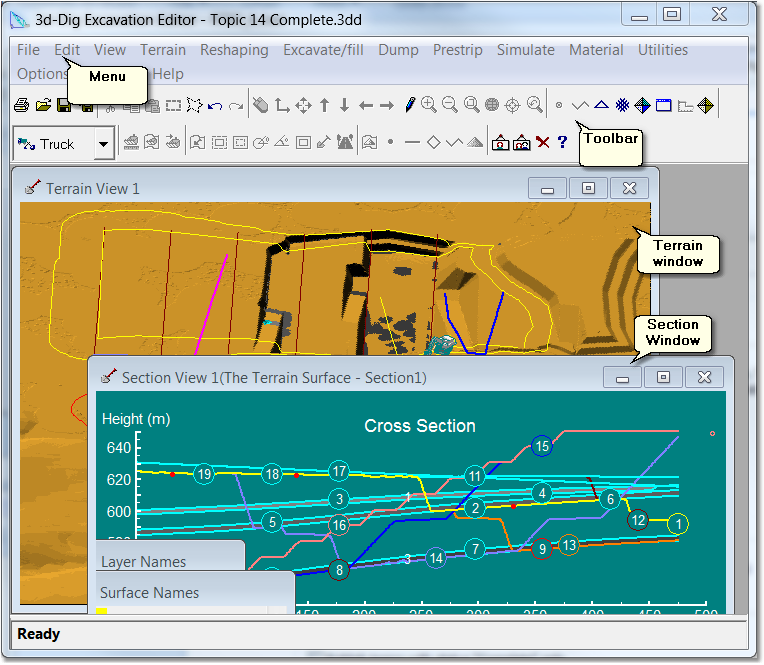
The figure below shows the 3d-DigPlus window with a file loaded:

3d-Dig Window.
The 3d-DigPlus window contains the following elements:
Menu. The menu provides access to all 3d-DigPlus functions and settings.
Toolbar. The toolbar provides access to the most commonly used 3d-DigPlus functions and settings.
Terrain Window. Terrain Windows display surfaces in 3d-DigPlus. These surfaces include the terrain, geological surfaces and design surfaces. These surfaces can be viewed in different modes as described in the following topic Terrain Windows and Surface Visualisation.
Section Window. Section Windows display cross-section information. They are also used to construct design elements, such as road vertical alignments, which must be constructed in a cross section view.
Windows Dialog Boxes (not shown in above figure). 3d-DigPlus uses a range of standard Windows dialog boxes to provide access to various functions and settings.
Specialised Dialog Boxes (not shown in above figure). 3d-DigPlus uses a number of specialised dialog boxes for access to some functionality. These dialog boxes generally have the behaviour of standard Windows dialog boxes with some additional functionality added. This additional specialised functionality is described in the appropriate sections of this documentation.