|
<< Click to Display Table of Contents >> Approximate Vertical Alignments |
  
|
|
<< Click to Display Table of Contents >> Approximate Vertical Alignments |
|
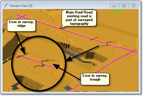
Approximate Vertical Alignments apply to Roads whose Vertical Alignments follow the topography generally but are independent of the topography in some areas. A common application of Approximate Vertical Alignments is where a Main Haul Road is placed on topography which contains a surveyed road but where an error or incomplete survey exists over portion of the road. Minor errors in aerial survey data can create small areas of very steep gradient along the alignment of an existing road. If the Road Vertical Alignment followed this survey strictly the steep gradients could result in either a substantial degrading of truck speed or potentially if the erroneous gradient is steeper than the trucks' maximum tolerable grade the truck could stall in the simulation.
As the simulation always takes place on the Roads' Vertical Alignment the above problem is easily circumvented simply by skipping the erroneous section of topography with the vertical alignment.
The following figures illustrate this situation. For clarity erroneous sections of topography have been exaggerated in these figures.
Terrain view showing Main All Road crossing area of survey error:
Longitudinal Section view showing Vertical Alignment negotiating survey errors:
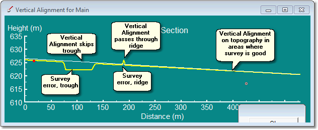
Using approximate Vertical Alignments in the above situation is as simple as drawing a Vertical Alignment to pass areas of survey error at an appropriate grade regardless of the topography.
Excavation and Dump Accesses frequently have a starting section which travels along topography before meeting the ramps which are part of the design surface. Sometimes this section of starting topography will contain the sorts of topographic errors described above and using the approach of Approximate Vertical Alignment is necessary to negotiate these errors. However in these situations is important to bear in mind the relationship between Vertical Alignment and topography used by 3d-DigPlus to establish the toe of Excavation Access for current lift during excavation, or the crest of Dump Access for current lift.
In the case of excavation 3d-DigPlus identifies the toe of the Excavation Access by identifying that point where the Vertical Alignment is no longer on the topography but below the topography. If and Approximate Vertical Alignment is used to negotiate an erroneous ridge, such as that shown in the figure above, the Vertical Alignment is below topography within this area, and if the depth of cover is greater than the tolerance used in determining Toe of Access, this may lead to an error in determining the correct Toe of Access during simulation. There are two methods of handling the situation:
•Use Excavate/Fill to remove the ridge from the topography.
•Use a Approximate Vertical Alignment which passes over, rather than through, the ridge.
The following figure illustrates these points:
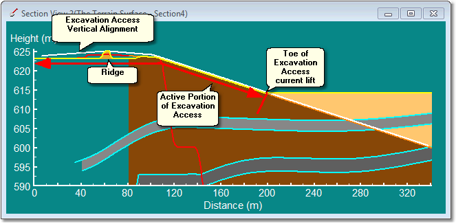
In the above figure the Toe of Excavation Access is clearly identified as the point where the Excavation Access Vertical Alignment leaves the level of the topography at the current lift and continues below the level of the topography (underground). If the Excavation Access Vertical Alignment was to pass through the erroneous ridge it would be located below the topography in this area and this may lead to problems with 3d-DigPlus identifying the correct Toe of Excavation Access. Hence in the above example the Vertical Alignment is placed so as to pass over the ridge. The alternative workaround for this problem is to use the excavate/fill command to remove the ridge altogether.
If a survey error consisting of a trough is encountered in the above situation the Approximate Vertical Alignment can pass over the trough without problem as it results in the Vertical Alignment being placed above topography and this does not mimic the relationship between alignment and topography used to establish the Toe of excavation Access.
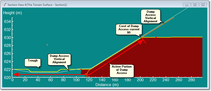
The above example deals with Approximate Vertical alignments in Excavation Access Roads. The situation with Dump Access Roads is very similar however the relationship between the Vertical Alignment and topography is the inverse of that for Excavation Access. The Crest of Dump Access is the point where the Vertical Alignment is no longer located on topography but is above topography (in the area to be filled with future dump lifts). 3d-DigPlus identifies this crest by locating the point where the Dump Access Road Vertical Alignment departs from the level of topography and is located above topography. If a ridge error exists (as in the example above) the Approximate Vertical Alignment can simply pass through this ridge without problem. However if a trough error exists the Approximate Vertical Alignment cannot be placed too far above topography. This problem can be overcome by either using Excavate/Fill to fill in the trough or creating an Approximate Vertical Alignment which passes down and follows approximately the level of the trough.
The figure below illustrates the use of an approximate Vertical Alignment in a Dump Access Road: