|
<< Click to Display Table of Contents >> Surface Reshaping |
  
|
|
<< Click to Display Table of Contents >> Surface Reshaping |
|
This section covers Spoil Reshaping and subdivided into perimeter spoil and interior spoil topics.
The first exercise involves reshaping the perimeter spoil as shown below to an angle of approximately 12°:
.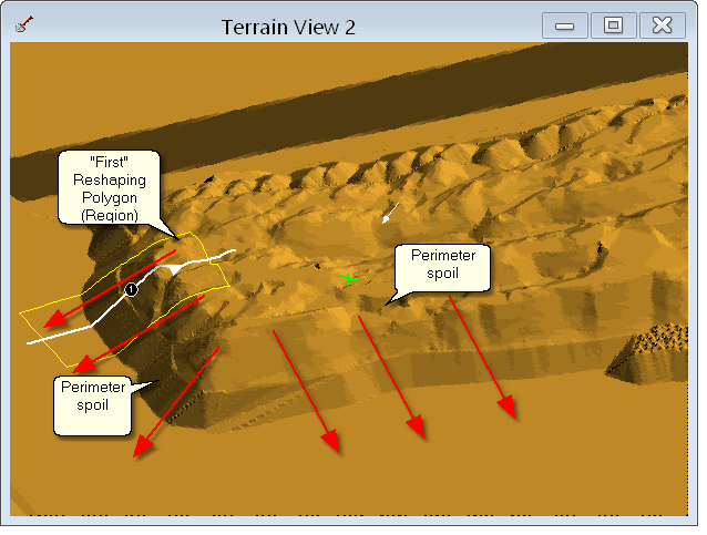
In this example the RL of the top of spoil around the perimeter and the RL of this surrounding topography are reasonably consistent. This means that the length of reshaped slope will be about the same around the design area. We start off by setting up an initial Polygon we refer to as the "first" Polygon. We then create a series of polygons for the full design area with similar geometry to this first polygon.
Throughout the design process we assess the fitness of the slope for the first Polygon by viewing a cross-section through this polygon running parallel with the primary slope. As the reshaped surface in the first polygon starts to approach the design slope, we set up a Contour window for the topography. By comparing contour spacing in the first polygon with that in other areas we can assess the fitness of slope in those other areas.
Load the file Reshape_Tut_1.3dd. The first stage in this process is to place the Reshaping Polygons for the perimeter region, The procedures involved are illustrated in the following video clip:
Once the Polygons are established the next task is to reshape the perimeter spoil to achieve a suitable design slope and form. The following video clip goes through this process.
In this exercise the design criteria is for a 12° overall slope and a small amount of S curvature. If less curvature is required this would mean further iterations of reshaping similar to those detailed in the following exercise.
Reducing long slopes with substantial volumes, such as this, can often involve substantial reshaping iterations. There will be stages in the process where the reshaping proceeds very slowly. That is to say a large number of iterations produce only a small reduction in slope. In these cases the process can be sped up by increasing the Iteration Step parameter or setting the Rarefaction Factor to 2.
Situations can also occur where the current settings (Steepness Coefficient, Iteration Step etc) appear to stall. That is to say with very large numbers of iterations only an extremely small slope reduction occurs. If this appears to be the case the parameters, particularly the Steepness Coefficient, should be modified and another run of iterations performed. In the following exercise this stalling condition has been deliberately included to demonstrate the above processes. With experience it should be possible to proceed in a more direct manner than that demonstrated in this exercise. Some experience is required to distinguish between the situation where the reshaping process has slowed towards the end of the slope reduction and that where it is effectively stalled. Keep in mind that the greatest slope reduction for each round of iterations occurs at the beginning of the process and slows as the slope approaches design.
The best sequence of reshaping parameters will vary with each individual case. However the following use of Straightness Coefficient is found to be effective in many cases:
•Initial round of reshaping Straightness Coefficient 2.0
•Main round of reshaping Straightness Coefficient 4.0
•Final slope reduction and curve straightening Straightness Coefficient 2.0.
Slopes are checked via a combination of cross-section and contours. Representative cross sections are placed normal to the primary slope within several reshaping Polygons. These cross sections are used to measure the overall slope, a contour terrain window is then used to assess slopes throughout the full design area. In this example two cross sections are used. If a tighter level of control over slope is required it may be necessary in some jobs to place cross sections within all reshaping Polygons. Alternatively the one cross-section can be moved and adjusted from Polygon to Polygon.This detailed process is generally only necessary towards the end of the reshaping process. That is to say the bulk of the reshaping should be performed before detailed slope checking is applied.
Some of the Polygons in this exercise require editing during the reshaping process. Even if you place polygons which are similar to those shown they are likely to be slightly different and hence you may find that you have to edit different polygons in a different manner to that shown. The example shown here should be taken as an example of the general principles and you should adapt this Polygon editing as required in your case. This exercise has been divided into two video clips. The first video clip deals with the setup and the initial round of reshaping. You should be able follow the steps in this video clip as they are described. The second video clip involves final rounds of reshaping and you should take the instructions as indicative only as you will need to modify these to suit your particular case.
To start the exercise load the previously saved file:
Reshape_Tut_2.3dd
Having completed the perimeter spoil this exercise moves on to a small area of interior dragline spoil as shown in the figure below:

Internal Spoil Area
This area of internal spoil consists primarily of two adjacent spoil crests and a common trough as shown below:

Internal Spoil - Cross Section.
Towards the northern end (right-hand side) end and additional row of spoil is included. There are a number of different approaches that can be applied to this situation:
1.Create one large Polygon to cover the entire area and reshape all spoil in one operation.
2.Create localised polygons which encompass both crests and the common trough.
3.Create localised Polygons which encompass only one crest and an adjacent portion of the trough.
Method 1 is the quickest approach but it can result in non-localised spoil balance. However a more significant problem is that some slopes will approach the design slope well in advance of others. Continuing to reshape in this situation until all slopes conform with design will result in those leading slopes being reduced significantly below the design criteria slope, and this will typically be unacceptable. This method can however be useful when a quick estimate of volumes and a schematic surface design are required. It can also be useful to pretreat an area of spoil and reshape until some slopes are at design. Localised Polygons can then be used to treat the remaining steep slopes.
Method 2 can be useful but it is only applicable when adjacent spoil crests have a similar elevation and geometry. If one spoil crest is significantly higher or larger than the other the problems described for method 1 will apply.
Method 3 is the most reliable method and this is the method we will apply in the following exercise.
Using method 3 to create polygons for internal spoil is somewhat similar to the methods applied for Polygon placement in perimeter spoil. The polygon should go from just beyond the crest to just beyond the centre of the adjacent trough. It is possible to use a cross-section approach, such as used for the perimeter spoil, but in the following exercise we will estimate the initial polygon location and adjust as required throughout the process. Cross sections will however be used to measure slopes.
When treating the perimeter spoil, due to the large volumes in large slope lengths, a very large number of reshaping iterations were required to produce a surface which was close to design slope. Due to the much shorter slope length and lesser volumes, internal spoil will typically reshape much more rapidly. In this situation there is a danger of "over reshaping" producing slopes significantly lower than design. Furthermore some internal slopes can be steep and long requiring large number of iterations while others require only a very small number of reshaping iterations. It is therefore important that care is taken to monitor the evolving slopes and ensure that polygons whose reporting slopes are close to design are not subject to further reshaping.
Be aware that even if you follow closely the Polygon placements suggested in this tutorial, is likely that your particular example will vary from that in the following video clip. You should be able to follow the instructions closely for the first round of polygon placement and reshaping. However as this surface approaches design slope the process of editing polygons and reshaping will vary from case to case and you should take this video clip as indicative only, modifying the procedures to suit your particular case.
To start the exercise load the previously saved file:
Reshape_Tut_3.3dd