|
<< Click to Display Table of Contents >> Setting up the Staging Parameters |
  
|
|
<< Click to Display Table of Contents >> Setting up the Staging Parameters |
  
|
Once a Pit with Block Lines is established and the Excavation Constraints are complete the Staging Parameters can be set up. This is achieved by selecting the Staging page of the Excavation Settings dialog.
As discussed in previous topics, the excavation of a strip is limited by the Strips' Pit Shell surface, and it is subdivided into increments by the Block Lines. Vertically the Strip is subdivided into Passes, and the Passes can be further subdivided into Lifts. This vertical subdivision is established via the parameters on the Staging page of the Excavation Settings dialog.
These Staging settings control the detail of how the excavation is subdivided vertically for automated excavation and simulation. The Staging setup involves firstly defining the area to be excavated and the passes, then establishing Pass Parameters to control the detail of how passes are excavated. Settings on the Staging page also control the way in which excavated volumes are logged.
The setup of the Staging parameters involves the following steps:
•Drawing a Limiting Polygon.
•Defining all Passes.
•Defining the Lifts for each Pass.
•Establishing Material Logs.
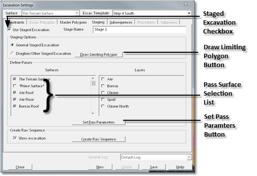
The Staging set up for the example pit is shown in the following figure:

Excavation Settings Dialog - Staging Page.
Setting up the staged excavation via the staging page involves the following settings:
•Use Staged Excavation. Checking this checkbox tells 3d-DigPlus that the current excavation template is to be used for a Staged Excavation, and enables the relevant fields on the staging page of the dialog box.
•General Staged Excavation. This selects the General type of Staged Excavation which is used for general and truck/shovel simulation
•Draw Limiting Polygon. The user must define the extents of the staged excavation, this is achieved by drawing a limiting polygon on the terrain. Typically staged excavations have a nominated Pit Shell surface. In principle this Pit Shell surface is sufficient to define the extents of the staged excavation. However a user-defined polygon is also required, see notes below.
•Select Pass Surfaces. The surfaces list contains all Inner Surfaces in the 3d-DigPlus file. Those surfaces which are to be used for passes in the excavation are selected via a checkbox. Typically these are the coal seams to be mined. However they may include specialised bench surfaces. Note that lift benches are typically handled by the pass parameters explained in the following section. 3d-DigPlus will automatically create a Pass for every surface selected in the Surfaces list starting at ground level (the Terrain Surface).
•Set Pass Parameters. Once the staging parameters are established and the Pass Surfaces selected, the Set Pass Parameters button is clicked and this opens up an additional dialog to refine the parameters for each nominated Pass. This dialog and the settings it contains are explained in the following section.
Key Information - Limiting Polygon
 The requirement for a limiting polygon as described above may appear unnecessary as the Pit Shell defines the extents of the excavation. However the limiting polygon is required to augment the pit Shell information for the following reasons:
•In some cases the Pit Shell surface may extend well beyond the area of the excavation and the excavation therefore needs to be limited to a subset of the area covered by the Pit Shell.
•Once the Pass Surfaces are selected and the Set Pass Parameters button is clicked 3d-DigPlus interrogates the pass surfaces and determines in what order they will be excavated. To do this successfully the assessment must be made within the area of the excavation. If the Pit Shell has a much greater extent than the actual excavation this can potentially lead to erroneous surface ordering.
•The use of Limiting Polygons provides an additional level of flexibility which allows some complex and non-standard excavations to be modelled.