|
<< Click to Display Table of Contents >> Excavation Access Roads with Virtual Vertical Alignments |
  
|
|
<< Click to Display Table of Contents >> Excavation Access Roads with Virtual Vertical Alignments |
|
Excavation Access Roads are required to have a dynamic behaviour, they must extend automatically as the excavation progresses. The principles used to achieve this dynamic behaviour are the same as those described above for excavation accesses where full ramp design exists. The two figures below illustrate a partially excavated Excavation Access Road modelled firstly with full ramp design and with Virtual Vertical Alignment:
Excavation Access with full ramp design:
Excavation Access with Virtual Vertical Alignment:
 |
| Click to toggle larger |
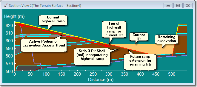
During simulation 3d-DigPlus must determine the portion of this access road used for each lift as it is excavated. This is achieved by establishing the toe of highwall ramp for current lift (see above figure). For any given lift, the Vertical Alignment of the Excavation Access road will be at the level of the topography for the length of the current highwall ramp and below topography for the length of the future ramp extension. The toe of highwall ramp for current lift is the point of transition where the Excavation Access Road's Vertical Alignment ceases to be located above topography and is located below topography. This is the point where trucks depart the Excavation Access Road and travel on the Excavation Manifold to the excavator. The portion of the Excavation Access Road above the toe of ramp for the current lift is called the Active Portion. In order for this method of locating the Active Portion of Excavation Access to work, the Excavation Access road must be located within the excavated zone for the strip to which it applies. If this is the case as each lift is excavated part of the Virtual Vertical Alignment will be located above the topography for a given lift (as shown in the figure above). If the Excavation Access Road is located beyond the high wall of the current strip it will be located in an area which is not excavated with the current strip. In this case it will not function properly as a dynamic Excavation Access.
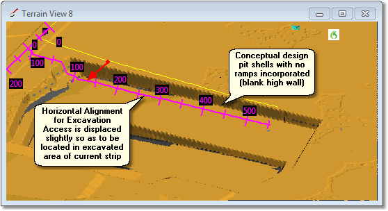
Virtual Vertical Alignments are generally applied to a conceptual design with a pit shells are "blank" and do not incorporate ramps. The Excavation Access Road with Virtual Vertical Alignments is intended to simulate a high wall ramp, this ramp will typically be located in the high wall. As such, the actual ramp will be located beyond the blank high wall. However if the Excavation Access Road is placed along the centreline of such a ramp it will be in an area not excavated by the current blank strip. Consequently such access roads must be displaced slightly so they are located within the excavation zone to the current strip. Generally this displacement will have only a minor effect on productivity, if necessary this can be compensated for by adjusting the Excavation Manifold parameters (see following topics). The following figures illustrate this:
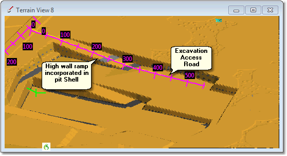
Excavation Access Road in pit with full ramp design incorporated:
Excavation Access Road in pit with conceptual pit shells with no ramps incorporated: