|
<< Click to Display Table of Contents >> Dump Access Roads with Virtual Vertical Alignments |
  
|
|
<< Click to Display Table of Contents >> Dump Access Roads with Virtual Vertical Alignments |
  
|
Dump Access Roads are required to have a dynamic behaviour, they must extend automatically as the dumping progresses. The principles used to achieve this dynamic behaviour are the same as those described in previous topics for dump accesses where full ramp design exists. The two figures below illustrate two partially completed Dump Access Roads the first is modelled with full ramp design and the second with a Virtual Vertical Alignment:

Dump Access Road, ramp design incorporated into dump design surface
 |
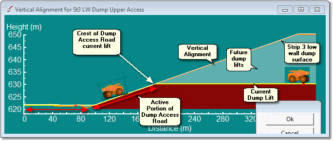
| Dump Access Road, no road design incorporated into dump design surface, Virtual Vertical Alignment used (Click to toggle larger) |
In order to establish the crest of Dump Access Road for the current lift 3d-DigPlus locates the point where the Vertical Alignment transitions from being on or below the topography to being above the topography. In the case of the example where the ramp is incorporated into the dump design surface, for any given lift the Active Portion of the Excavation Access Road has a Vertical Alignment which is on or very close to the topography for the current lift.
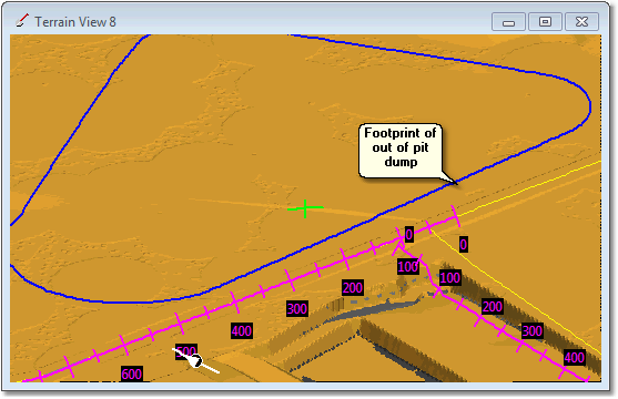
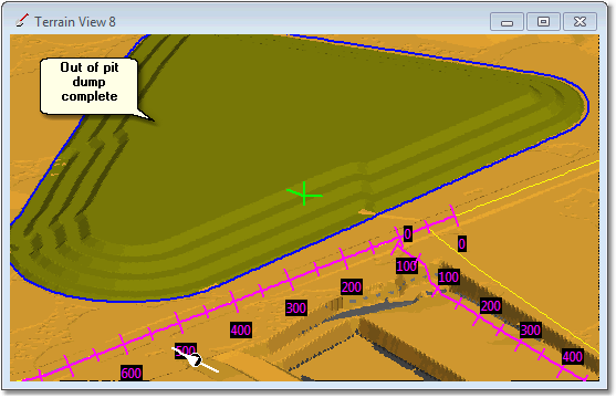
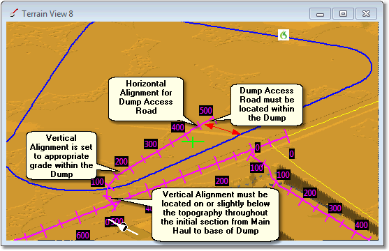
In the case of the example which uses a Virtual Vertical Alignment, Vertical Alignment is typically well below the topography ("inside" the dump) and it emerges from below the topography at the point of the crest of Dump Access for the current lift.in order to ensure this process works reliably, it is important that the Virtual Vertical Alignment is located within the volume of the dump it services. The Vertical Alignment should be on or slightly below the topography for the initial section from the Haul Road junction to the base of the Dump, and thereafter within the Dump. The following figures illustrate this:

Proposed out of pit dump

Proposed out of pit dump complete

Dump Access Road for proposed out of pit dump
The procedure for creating a Dump Access with Virtual Vertical Alignment is as follows:
•Decide the type of ramp and ramp geometry that will be used to service the dump and add a Surface Feature to follow approximately expected alignment of this ramp.
•Determine if this alignment will be comfortably within the Dump as it is constructed. If the alignment is too close to the edge of the dump, move it slightly inside.
•Create a new road for the Dump Access, place a horizontal alignment along the Surface Feature constructed.
•Create a Vertical Alignment which is on or slightly below terrain from the junction with the Main All Road to the base of Dump, and is entirely within the dump for the remainder. Ensure that this alignment has the appropriate gradient within the dump.
The following topic shows an example of creating a Dump Access Road with Virtual Vertical Alignment.