|
<< Click to Display Table of Contents >> Excavation Access - General & Haul up Option |
  
|
|
<< Click to Display Table of Contents >> Excavation Access - General & Haul up Option |
|
The set up of roads for use in Excavation Access will be demonstrated here by the use of example. For this example the pit used has a parallel high wall ramp. It is assumed initially that all material will be hauled up the ramp and out of pit. This situation where material is hauled up the ramp from the point of excavation is a particular mode of operation for Excavation Access Roads and is called the Haul up option. There is also a Haul Down option detailed in the following section. Haul up and Haul Down are a subset of the Excavation Access mode of operation and as such this distinction (Haul up or Haul Down) is set at the time Roads are assigned to Subsequences.
The following figures illustrate the starting state of the strip and the ramp, and intermediate state and the State on completion of the strip.
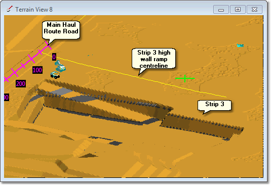
Strip 3 start of strip:
Strip 3 partially excavated:
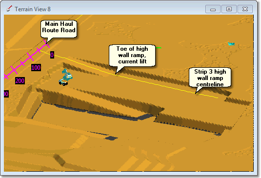
In the above figure trucks leaving the excavator will travel along the Excavation Manifold to the toe of the high wall ramp at the current lift, and then up the ramp to the Main Haul Route.
Strip 3 complete:
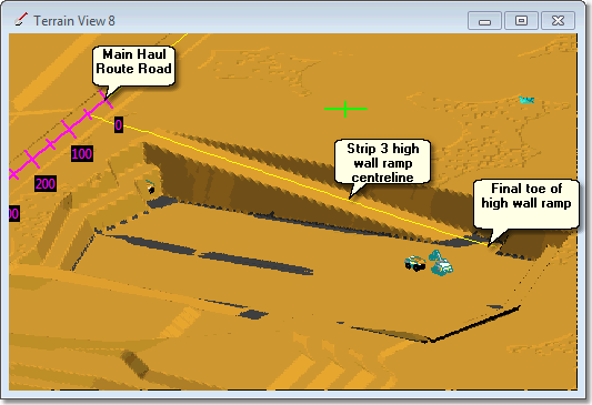
From the above figures it is clear that the Excavation Access Road created to model this high wall ramp must be designed through to the floor of Strip 3, but must have the capacity to gradually extend from the surface down with each subsequent lift.
In the above example the Strip 3 Pit Shell has the high wall ramp designed in. The figure below shows a longitudinal section along the centreline of the high wall ramp when Strip 3 is partially excavated:
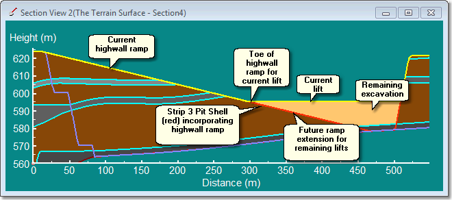
The key features in the above figure are:
Strip 3 Pit Shell. The design surface for the strip currently being excavated, Strip 3.
Current lift. The floor of the last lift excavated and the roof of the next lift.
Current highwall Ramp. The current portion of the ramp excavated from the Strip 3 Pit Shell down to the current lift.
Future ramp extension. The ramp that will exist as further lifts are excavated.
Toe of highwall ramp for current lift. This is the point where the highwall ramp ends in the current lift.
The 3d-DigPlus Excavation Access Road is designed for the full length of the highwall ramp, it includes the existing and future ramp sections shown in the above figure. The Vertical Alignment of the Excavation Access Road follows the ramp design, so it follows the current highwall ramp and future ramp extension portions shown above.
During simulation 3d-DigPlus must determine the portion of this access road used for each lift as it is excavated. This is achieved by establishing the toe of highwall ramp for current lift (see above figure). For any given lift, the Vertical Alignment of the Excavation Access road will be at the level of the topography for the length of the current highwall ramp and below topography for the length of the future ramp extension. The toe of highwall ramp for current lift is the point of transition where the Excavation Access Road's Vertical Alignment ceases to be located on topography and is located below topography. This is the point where trucks depart the Excavation Access Road and travel on the Excavation Manifold to the excavator. The portion of the Excavation Access Road above the toe of ramp for the current lift is called the Active Portion.
3d-DigPlus detects the toe of the Excavation Access Road for a given lift by finding the point where its Vertical Alignment transitions from on topography to below.
Key Information - Excavation Access Road Vertical Alignment and ramp toe for current lift.
 3d-DigPlus determines the current toe of an access ramp by finding the point where the Excavation Access Road's Vertical Alignment ceases to be located on topography and is located below topography (ie goes from on ground to below ground). 3d-DigPlus starts at the point where the Excavation Access road joins the Main Haul Road, and progresses along the road comparing the level of the Vertical Alignment (VA) with the level of the topography. If the VA level is at or above topography, that portion of the Excavation Access is deemed to have been excavated and is part of the Excavation Access for the current lift. Using this method the toe of ramp for current lift and the Active Portion of the ramp are established. In applying the above rule 3d-DigPlus does add a small threshold value to the roads elevation.
In order for the above methodology to work the Vertical Alignment for the Excavation Access road must be at or slightly above topography. 3d-DigPlus does apply a small tolerance, so the VA can be slightly below ground and the process will work. However you should aim to place all points on the VA as close as reasonably possible to the final excavated topography.
The most common cause of problems with this process is in the region where the Access Road travels along topography for a distance before entering the zone of the excavation or dump. Often the natural topography can be quite irregular in this region. Figure below illustrates this for an Excavation Access:
 |
| Click to Toggle Larger |
It can be seen in the figure above that there is a mound in the topography between the crest of the endwall (limit of excavation) and the junction with the Main Haul Road (leftmost side). If the Vertical Alignment was to travel horizontally through this section there is a danger that the depth of cover over the Vertical Alignment may be greater than the threshold. To overcome this in the above example Vertical Alignment has been nudged upwards to minimise this cover. When using this method is important to ensure that the resultant gradients in the road are not large enough to significantly influence truck speeds and productivity. An alternative workaround is to use Excavate/Fill to excavate the topography and remove the mound.
The following video clip illustrates these concepts: