|
<< Click to Display Table of Contents >> Dozer Module Principles of Operation |
  
|
|
<< Click to Display Table of Contents >> Dozer Module Principles of Operation |
  
|
The dozer simulation module consists of two components:
•Topographic Simulation System.
•Dozer Dynamics Model.
The topographic simulation system simulates the manner in which the dozing operation incrementally modifies the starting topography to produce the final (target) topography. The dozer dynamics module establishes the three-dimensional paths travel by the dozer for each increment produced by the topographic simulation system and establishes the dozer blade loads, speeds and cycle times. Using the information generated the total development time for the operation modelled is determined.
The bulldozer productivity model simulates bulldozer dynamics in order to estimate cycle time, productivity and total dozing time for an incremental operation.
Dozing time is calculated as:
Dozing Time = S (Number of cycles in current increment) ´ (Time of each cycle)
The number of cycles in the current increment is calculated from
Number of cycles in current increment = (Volume of increment) / (Volume moved per cycle).
The volume moved per cycle is calculated using parameters described below.
The time of each cycle in a slice is taken as constant, since an average path is taken for the increment. This time is calculated as:
Time of each cycle = S (Time of each bulldozer path delta-step + Gear change loss time )+ Dead time
The gear change loss time is included only if a gear change occurs from the last step, and the dead time is added once only for each cycle. The time of each small delta-step is calculated as
Time of each bulldozer path delta-step = (step length) / (bulldozer speed for step)
The bulldozer speed for each step is calculated from the operating curve of the drawbar pull versus speed, as described below.
For a given bulldozer weight, the blade load and the angle of the drawbar pull are calculated from a static force diagram as follows:

Forces acting on Dozer.
The weight used is that of the bulldozer plus its material load in tonnes or tons. The Friction resistance is a general term for all the resistance to movement and pushing of the load that the bulldozer experiences. The friction is related to the normal reaction by
F = µ N.
Here µ is the “Friction Resistance Coefficient” (a model parameter). Balancing the forces along and perpendicular to the slope then gives:
N = W cos θ
and
F + W sin θ = P
Hence, at balance (constant speed), the drawbar pull is:
P = µ W cos θ + W sin θ
Calculation of Bulldozer Speed from Drawbar Pull
The bulldozer “speed” versus “drawbar pull” curves allow the speed of the bulldozer to be calculated at each point along its average path. This speed is then used to calculate a time for the path by breaking the path into short steps, taking a fixed average speed for each step and summing the resulting times taken for all steps.
The bulldozer is assumed to have three forward and three reverse gears. The speed versus drawbar pull curve in each gear is taken to be a straight line determined by two parameters:
Maximum drawbar pull per ‘bulldozer weight’ (at zero speed)
Maximum speed (at zero pull)
The first parameter is assumed to be the same in a given forward or reverse gear, while the maximum speed is different between forward and reverse. Taken together, the three curves for the three gears define a “working envelope” that is the drawbar pull versus speed curve for the machine. This is illustrated in the Figure below:
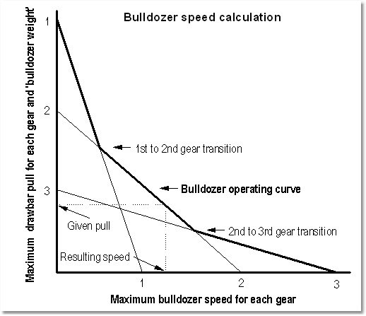
Dozer Rimpul Curve
For a given drawbar pull, the bulldozer speed is given by the highest possible speed in any gear. This assumes optimum gear changing. A “gear change lost time” parameter is introduced to allow for sub-optimal gear changes. This is added to the cycle time whenever a gear change is detected.
The following figures show the Dozer Parameters dialog box pages:
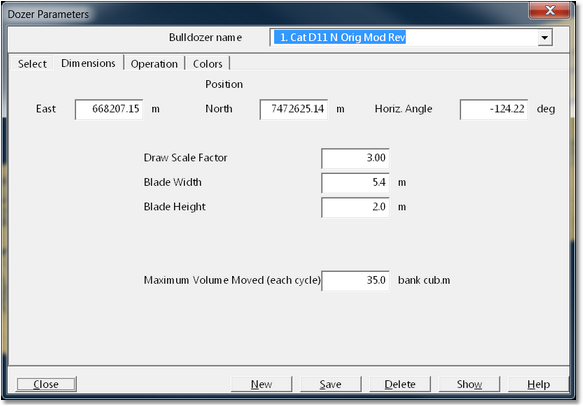
Dozer Parmaters Dialog - Dimensions Page.
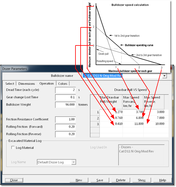
Dozer Parameters Dialog - Operation Page.
The operational parameters are defined below.
Dead time per cycle: Time period that is added to the theoretically calculated cycle time.
Bulldozer weight: Gross machine weight in tonnes or tons.
Gear change lost time: A fixed time loss associated with each gear change.
Friction resistance coefficient: This is the standard mechanics "friction coefficient" that also includes all forces (except weight) that resist the movement of the bulldozer's load. These include the effect of the resistance of uneven terrain on the blade and slipping of the treads under load. The value of this coefficient needs to be determined from measurement of the bulldozer’s speeds under load. Hence, it is expected that the coefficient will greater than unity.
Rolling Friction (Forward). This is the friction associated with movement of the unladen bulldozer in the forward direction.
Rolling Friction (Reverse). This is the friction associated with movement of the unladen bulldozer in the reverse direction.
Drawbar pull versus speed matrix: This details the maximum drawbar pull and maximum speed for each gear. This data is taken from bulldozer manufacturer’s drawbar pull versus speed curves. Drawbar pull is expressed here as a proportion of the machine gross weight in tonnes or tons.
Gear Transitions: The gear transition data is calculated from the intersections of the Drawbar Pull versus the Travel Speed curves for each speed. At present a fixed curve shape, based on bulldozer manufacturers' data, is used. Changing the maximum drawbar pull and maximum speed in each gear changes this intersection point, and gives users some flexibility to "tune" the Bulldozer productivity to their particular machine.
The topographic simulation system takes as input are starting topography and a target (design) topography. Using a variety of parameters set by the user the system then simulates the incremental movement of material required to produce the target topography.
The optimisation engine determines the optimal dozing sequence working within the defined balance regions. It takes as input the design topography, final topography and bulldozer parameters.
In order to do its work the optoimization engine requires the following functions:
Generation of feasible dozing sequences. A feasible dozing sequence must transport all material from cut to fill, progressing through a series of incremental steps, with each step having a feasible bulldozer trajectory. Each incremental step models the excavation transport and dumping of a thin layer of material.
Parameterisation of feasible dozing sequence. The system must utilise a set of geometric parameters for generating a feasible dozing sequence. These parameters must be the key parameters in determining the efficiency of the dozing operation.
Search and optimise. The optimisation function must be able to generate and assess a large number of feasible solutions in order to determine the optimal sequence
Report and animate. Having determined the optimal sequence the system must generate a report of the optimal parameters and a animation of the sequence.
Generation of feasible dozing sequences.
The generation of feasible a feasible dozing sequence required the following conditions to be met:
The volume of excavated material must be determined and a swell factor applied. This process must account for prime and rehandled material.
The dump must be accurately simulated, with material rilling onto the topography at the appropriate repose angle.
The bulldozer trajectory for each increment of the sequence must not exceed the maximum allowable slopes and grade changes defined in the bulldozer parameters.
The first two points are address by 3d-dig’s existing excavation and dump functionality.
The suitability of the bulldozer trajectory is controlled by the parameterisation of the feasibly sequence. The system constrains the parameters of each sequence to ensure feasibility.
Parameterization of feasible dozing sequences.
The following describes the parameterisation in the context of the auxiliary cross pit dozing mode. This mode uses the full suite of available parameters.
The primary parameters are:
Intermediate excavation surfaces. The excavation proceeds from the starting topography to the final topography via a set of intermediate excavation surfaces. The following figures show the intermediate excavation surface in the early stages of a sequence.
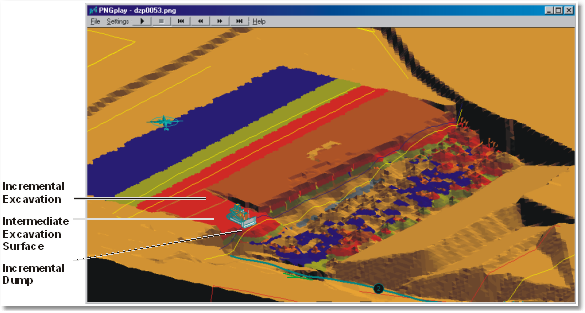
Dozer Sequence Stage 1
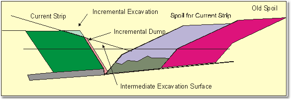
Dozer Sequence Stage 1 Section View.
The intermediate excavation surface has four design parameters in two groups:
•Initial slope. This is the gradient of the first (uppermost) surface. There are two initial slope parameters, one for downhill pushing and one for uphill.
•Slope variant. This is an angle increment that is applied each time a new intermediate surface is generated. There are two slope variant parameters, one for downhill pushing and one for uphill.
Bridge Surface. The “excavate and stack” methods (auxiliary cross pit dozing and subsurface excavation) involve transporting and dumping material along trajectories that are distinct from the excavation trajectory. We define the bridge and dump trajectories for the purpose of modelling. This is illustrated in the following figure:
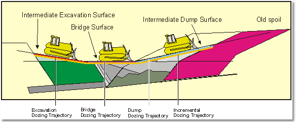
Bulldozer Trajectories, Excavate and Stack Methods.
Cross pit dozing operations typically commence with material being dozed off an edge with slope that is at, or greater than, repose angle (as illustrated in Figure 61). Dozing continually extends this edge and at some point spoil must be pushed across the pit. This transition from downhill to cross pit pushing is controlled by the bridge surface parameter. The bridge surface is a surface connecting the excavation and dump surfaces. It contains a volume of material occupying the wedge between the current strip’s overburden and spoil. The bridge surface is typically horizontal or has moderate slope. The following figures illustrate the bridge surface.
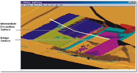
Bridge Surface.
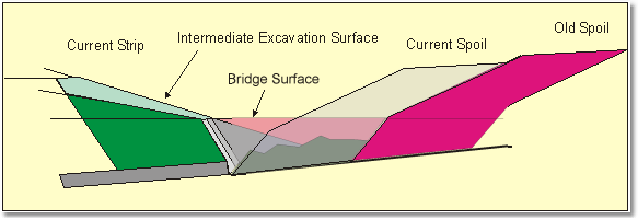
Bridge Surface - Section View.
Intermediate Dump Surfaces. “Excavate and stack” methods involve placing at least some of the excavated material at an elevation at or greater than the excavation point.This is shown in figure 62.
The intermediate dump surface has four design parameters in two groups:
•Initial slope. This is the gradient of the first (uppermost) surface. There are two initial slope parameters, one for downhill pushing and one for uphill.
•Slope variant. This is an angle increment that is applied each time a new intermediate surface is generated. There are two slope variant parameters, one for downhill pushing and one for uphill.
Incremental Dozing Trajectories. Each step modelled involves an incremental excavation surface, bridge surface and incremental dump surface, over which the bulldozer must travel. This path over which the bulldozer must travel is called the incremental dozing trajectory (see figure above).
Incremental Dozing Operations. The set incremental components described above collectively form an incremental dozing operation. In each incremental dozing operation a layer of material is excavated, transported and dumped.
Incremental Dozing Operations. The set incremental components described above collectively form an incremental dozing operation. In each incremental dozing operation a layer of material is excavated, transported and dumped:
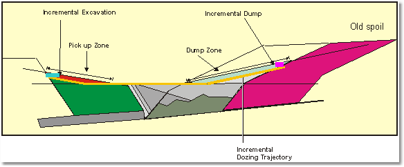
Incremental Dozing Operation.
Incremental Dump Location.
The Dozer settings include an option which controls location of each incremental dump. The two options are Fill Start Earlier all Fill Start End. With Fill Start Earlier the material will dump at the start of the dump surface relative to the current excavation location (i.e. excavated material will be dumped as close to the excavate point as possible subject to being within the defined dump). When Excavate Surfaces and Dump Surfaces are used the Start Fill Earlier option will result in material being pushed out at the end of the current excavate zone. With many dozing operations this option is necessary as the dozer must use this type of process to produce a suitable surface on which to travel. When using Excavate Surfaces and Bridge Surfaces the Start Fill Earlier option is generally required.