|
<< Click to Display Table of Contents >> Dump Access Roads |
  
|
|
<< Click to Display Table of Contents >> Dump Access Roads |
|
The process of progressively constructing a Staged Dump has a requirement for flexible road access very similar to that required for staged excavations. These requirements are met in 3d-DigPlus via the use of Dump Access Roads. As discussed above, there is only one Road type in 3d-DigPlus, and all roads, including Dump Access Roads, are of this type. Dump Access is a mode of operation of a Road. Roads are designed to meet the requirements of dump access and the dump access mode of operation is determined at the time the Road is assigned to a Subsequence.
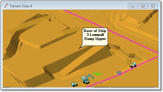
The following figures illustrate a typical dump access situation. This example is for a low wall dump, Strip 3 Low wall Dump Upper. This Dump is constrained by design surface which incorporates a ramp. The Dump Access Road runs along the centreline of this ramp, and the Vertical Alignment for this access road follows the ramp in the design surface.
Topography at commencement of Strip 3 Lowwall Dump Upper:
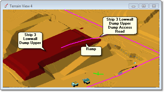
Topography at completion of Strip 3 Lowwall Dump Upper:
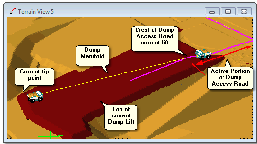
The above Dump will be constructed in lifts as a Staged Dump. During the construction of each lift 3d-DigPlus must determine the Active Portion of the Dump Access Road. To do this it must determine the crest of the Dump Access Road for each lift. The following to figures illustrate this:
Longitudinal section through Dump Access Road:
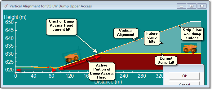
As can be seen in the cross-section above, the Excavation Access Roads Vertical Alignment is coincident with the topography throughout the Active Portion up to crest of Dump Access Road. Beyond the crest of the Dump Access Road the Vertical Alignment diverges from the topography and is located above the topography of the current lift.
3d-DigPlus identifies the crest of the Dump Access Roads by locating the point where the Vertical Alignment diverges from the topography. In order for this process to work it is important that the Vertical Alignment is coincident with the evolving topography of the Dump as each lift is placed. To achieve this the Vertical Alignment follows the Dump design surface as shown in the figure above. Note that 3d-DigPlus does apply a small tolerance so the Vertical Alignment does not need to follow the design surface precisely, however it does need to be close.
Key Information - Dump Access Road Vertical Alignment and ramp toe for current lift.
 3d-DigPlus determines the current toe of an access ramp by finding the point where the Dump Access Road's Vertical Alignment ceases to be located on topography and is located above topography (ie goes from on ground to above ground). 3d-DigPlus starts at the point where the Excavation Access road joins the Main Haul Road, and progresses along the road comparing the level of the Vertical Alignment (VA) with the level of the topography. If the VA level is at or below topography, that portion of the Excavation Access is deemed to have been dumped on and is part of the Dump Access for the current lift. Using this method the toe of ramp for current lift and the Active Portion of the ramp are established. The video clip below illustrates this.
In order for the above methodology to work the Vertical Alignment for the Dump Access road must be at or slightly below topography. 3d-DigPlus does apply a small tolerance, so the VA can be slightly above ground and the process will work. However you should aim to place all points on the VA as close as reasonably possible to the final excavated topography.
The most common cause of problems with this process is in the region where the Access Road travels along topography for a distance before entering the zone of the excavation or dump. Often the natural topography can be quite irregular in this region. Figure below illustrates this for a Dump Access:
 |
| Click to Toggle Larger |
It can be seen in the figure above that there is a hollow in the topography between the crest of the dump (limit of dump) and the junction with the Main Haul Road (leftmost side). If the Vertical Alignment was to travel horizontally above this hollow section there is a danger that the clearance of the Vertical Alignment above the topography may be greater than the threshold. To overcome this in the above example Vertical Alignment has been nudged downwards to minimise this cover. When using this method it is important to ensure that the resultant gradients in the road are not large enough to significantly influence truck speeds and productivity. An alternative workaround is to use Excavate/Fill to fill the hollow in the topography.
A Dump Manifold connects the Crest of Dump Access Road to the tip point. In the above figures a single dump point is shown at the tip face. A Dump point and manifold is established for each block of material dumped.
The following video clip demonstrates the application of Dump Access Roads: